Main rotor rotational speed control for rotorcraft
Weiner , et al. J
U.S. patent number 10,167,079 [Application Number 15/508,346] was granted by the patent office on 2019-01-01 for main rotor rotational speed control for rotorcraft. This patent grant is currently assigned to SIKORSKY AIRCRAFT CORPORATION. The grantee listed for this patent is SIKORSKY AIRCRAFT CORPORATION. Invention is credited to William J. Eadie, Steven D. Weiner.
View All Diagrams
| United States Patent | 10,167,079 |
| Weiner , et al. | January 1, 2019 |
Main rotor rotational speed control for rotorcraft
Abstract
An aircraft includes an airframe having an extending tail, a counter rotating, coaxial main rotor assembly disposed at the airframe including an upper rotor assembly and a lower rotor assembly and a translational thrust system positioned at the extending tail and providing translational thrust to the airframe. A flight control computer is configured to control a main rotor rotational speed of the upper and the lower rotor assemblies of the main rotor assembly as a function of airspeed of the aircraft. A method of operating an aircraft includes retrieving a threshold main rotor rotational speed of the dual coaxial main rotor assembly and calculating an actual main rotor rotational speed according to an environment of the aircraft. The actual main rotor rotational speed is maintained to remain at or below the threshold main rotor speed according to an airspeed of the aircraft.
| Inventors: | Weiner; Steven D. (Orange, CT), Eadie; William J. (Cheshire, CT) | ||||||||||
|---|---|---|---|---|---|---|---|---|---|---|---|
| Applicant: |
|
||||||||||
| Assignee: | SIKORSKY AIRCRAFT CORPORATION
(Stratford, CT) |
||||||||||
| Family ID: | 55631217 | ||||||||||
| Appl. No.: | 15/508,346 | ||||||||||
| Filed: | September 29, 2015 | ||||||||||
| PCT Filed: | September 29, 2015 | ||||||||||
| PCT No.: | PCT/US2015/052802 | ||||||||||
| 371(c)(1),(2),(4) Date: | March 02, 2017 | ||||||||||
| PCT Pub. No.: | WO2016/053944 | ||||||||||
| PCT Pub. Date: | April 07, 2016 |
Prior Publication Data
| Document Identifier | Publication Date | |
|---|---|---|
| US 20170283047 A1 | Oct 5, 2017 | |
Related U.S. Patent Documents
| Application Number | Filing Date | Patent Number | Issue Date | ||
|---|---|---|---|---|---|
| 62058424 | Oct 1, 2014 | ||||
| Current U.S. Class: | 1/1 |
| Current CPC Class: | B64D 35/06 (20130101); B64C 27/52 (20130101); B64C 27/008 (20130101); G05D 1/0077 (20130101); B64C 27/78 (20130101); B64C 27/001 (20130101); B64C 19/00 (20130101); B64C 27/006 (20130101); B64C 27/16 (20130101); G05D 1/0858 (20130101); B64C 27/10 (20130101); B64C 27/32 (20130101); B64D 45/02 (20130101); B64C 27/82 (20130101); B64D 39/06 (20130101); F16H 37/02 (20130101); B64C 27/33 (20130101); B64C 27/12 (20130101); B64C 27/467 (20130101); B64C 27/14 (20130101); B64C 27/473 (20130101); B64C 13/18 (20130101); B64C 27/322 (20130101); B64C 27/51 (20130101); B64C 27/54 (20130101); G05D 1/0816 (20130101); F16F 15/02 (20130101); B64C 13/50 (20130101); B64C 27/80 (20130101); B64C 7/00 (20130101); B64C 13/503 (20130101); B64C 13/04 (20130101); G05D 1/0202 (20130101); B64D 39/00 (20130101); B64C 27/48 (20130101); B64C 27/57 (20130101); B64C 1/0009 (20130101); F05D 2270/021 (20130101); B64C 2201/024 (20130101); F02C 9/28 (20130101); B64C 2027/8272 (20130101); G05D 1/08 (20130101); B64C 2027/8281 (20130101); F16D 13/72 (20130101); B64C 27/08 (20130101); G05D 1/0204 (20130101); B64C 2027/8263 (20130101); F05D 2220/329 (20130101); B64C 2027/004 (20130101); B64C 2027/8227 (20130101); B64C 2027/8209 (20130101); B64C 2027/8236 (20130101); F16D 13/52 (20130101); F16D 13/74 (20130101) |
| Current International Class: | G05D 1/00 (20060101); B64C 27/14 (20060101); B64C 13/04 (20060101); B64C 13/18 (20060101); G05D 1/08 (20060101); B64C 13/50 (20060101); B64C 27/57 (20060101); G05D 1/02 (20060101); B64C 27/00 (20060101); B64D 39/00 (20060101); B64D 39/06 (20060101); B64C 27/80 (20060101); B64D 35/06 (20060101); F16H 37/02 (20060101); B64C 27/51 (20060101); B64C 27/52 (20060101); B64C 27/32 (20060101); B64C 27/12 (20060101); B64C 27/10 (20060101); B64C 27/82 (20060101); B64C 27/33 (20060101); B64D 45/02 (20060101); B64C 7/00 (20060101); B64C 27/467 (20060101); B64C 27/78 (20060101); B64C 27/54 (20060101); B64C 19/00 (20060101); B64C 1/00 (20060101); B64C 27/16 (20060101); B64C 27/48 (20060101); B64C 27/473 (20060101); F16D 13/52 (20060101); F16D 13/72 (20060101); F16D 13/74 (20060101); B64C 27/08 (20060101); F02C 9/28 (20060101) |
| Field of Search: | ;701/3 |
References Cited [Referenced By]
U.S. Patent Documents
| 1344486 | June 1920 | Coffelt |
| 2344967 | March 1944 | Bennett |
| 2469144 | May 1949 | Baggott |
| 2482460 | September 1949 | Browne |
| 2557127 | June 1951 | Magill |
| 2582609 | January 1952 | Steele |
| 2665859 | January 1954 | James |
| 2698147 | December 1954 | Hovgard |
| 2814451 | November 1957 | Turner et al. |
| 2980186 | April 1961 | Strong et al. |
| 3002420 | October 1961 | Willits et al. |
| 3029048 | April 1962 | Earnest et al. |
| 3217811 | November 1965 | Hibyan et al. |
| 3310120 | March 1967 | Vacca |
| 3327969 | June 1967 | Head |
| 3331444 | July 1967 | Toner |
| 3332643 | July 1967 | Toner |
| 3351304 | November 1967 | Stein et al. |
| 3409249 | November 1968 | Bergquist |
| 3421717 | January 1969 | Di Piro |
| 3521971 | July 1970 | Cheney, Jr. |
| 3570786 | March 1971 | Lewis |
| 3591109 | July 1971 | McLarty |
| 3599907 | August 1971 | Ransom et al. |
| 3822105 | July 1974 | Jepson |
| 4008979 | February 1977 | Cooper et al. |
| 4020324 | April 1977 | Buscher et al. |
| 4114843 | September 1978 | Robinson |
| 4142837 | March 1979 | De Simone |
| 4168045 | September 1979 | Wright et al. |
| 4248572 | February 1981 | Fradenburgh |
| 4304375 | December 1981 | Builta et al. |
| 4332525 | June 1982 | Cheney, Jr. |
| 4334828 | June 1982 | Moffitt |
| 4375940 | March 1983 | Lovera et al. |
| 4386848 | June 1983 | Clendenin et al. |
| 4392781 | July 1983 | Mouille et al. |
| 4531692 | July 1985 | Mateus |
| 4573873 | March 1986 | Yao et al. |
| 4583626 | April 1986 | Spridco |
| 4681511 | July 1987 | Glatfelter |
| 4704070 | November 1987 | Iseman |
| 4730795 | March 1988 | David |
| 4825375 | April 1989 | Nadkarni et al. |
| 4856483 | August 1989 | Beavis et al. |
| 4928907 | May 1990 | Zuck |
| 5005439 | April 1991 | Jensen et al. |
| 5058824 | October 1991 | Cycon et al. |
| 5096383 | March 1992 | Dobrzynski |
| 5213283 | May 1993 | Gold et al. |
| 5219143 | June 1993 | Staple et al. |
| 5222691 | June 1993 | Gold et al. |
| 5238203 | August 1993 | Skonieczny et al. |
| 5240204 | August 1993 | Kunz |
| 5253979 | October 1993 | Fradenburgh et al. |
| 5427336 | June 1995 | Haggerty et al. |
| 5454530 | October 1995 | Rutherford et al. |
| 5527004 | June 1996 | Haggerty et al. |
| 5614908 | March 1997 | Phelan et al. |
| 5797105 | August 1998 | Nakaya et al. |
| 5845236 | December 1998 | Jolly et al. |
| 5914691 | June 1999 | Mandai et al. |
| 6086016 | July 2000 | Meek |
| 6086975 | July 2000 | Brick et al. |
| 6098921 | August 2000 | Piasecki |
| 6198991 | March 2001 | Yamakawa et al. |
| 6322324 | November 2001 | Kennedy et al. |
| 6448924 | September 2002 | Hafer, Jr. |
| 6460802 | October 2002 | Norris |
| 6467726 | October 2002 | Hosoda |
| 6497385 | December 2002 | Wachspress et al. |
| 6533549 | March 2003 | Schreiber et al. |
| 6592071 | July 2003 | Kinkead et al. |
| 6641365 | November 2003 | Karem |
| 6655631 | December 2003 | Brown |
| 6793173 | September 2004 | Salesse-Lavergne |
| 6885917 | April 2005 | Osder et al. |
| 6886777 | May 2005 | Rock |
| 6905091 | June 2005 | Berson et al. |
| 6929215 | August 2005 | Arlton |
| 7017857 | March 2006 | Hill et al. |
| 7210651 | May 2007 | Scott |
| 7229251 | June 2007 | Bertolotti et al. |
| 7264199 | September 2007 | Zientek |
| 7296767 | November 2007 | Palcic et al. |
| 7434764 | October 2008 | Lappos et al. |
| 7438259 | October 2008 | Piasecki et al. |
| 7440825 | October 2008 | Einthoven et al. |
| 7448571 | November 2008 | Carter, Jr. |
| 7451949 | November 2008 | Eglin |
| 7461819 | December 2008 | Eglin |
| 7471057 | December 2008 | Clary |
| 7513750 | April 2009 | Moffitt et al. |
| 7530787 | May 2009 | Bertolotti et al. |
| 7530790 | May 2009 | Cabrera et al. |
| 7582032 | September 2009 | Manfredotti |
| 7584923 | September 2009 | Burrage |
| 7585153 | September 2009 | Schmaling et al. |
| 7600976 | October 2009 | Bagai et al. |
| 7604198 | October 2009 | Petersen |
| 7621480 | November 2009 | Darrow, Jr. et al. |
| 7628355 | December 2009 | Palcic et al. |
| 7648338 | January 2010 | Welsh |
| 7674091 | March 2010 | Zierten |
| 7758310 | July 2010 | Cotton et al. |
| 7823827 | November 2010 | Piasecki et al. |
| 7836701 | November 2010 | Zack et al. |
| 7841829 | November 2010 | Schmaling et al. |
| 7857252 | December 2010 | Walliser et al. |
| 7857598 | December 2010 | McGeer et al. |
| 7874526 | January 2011 | Boczar et al. |
| 7908044 | March 2011 | Piasecki et al. |
| 7930074 | April 2011 | Cherepinsky et al. |
| 7942365 | May 2011 | Palcic et al. |
| 7967239 | June 2011 | Cotton et al. |
| 8019490 | September 2011 | Ferren et al. |
| 8036821 | October 2011 | Cornett et al. |
| 8052094 | November 2011 | Roesch |
| 8052097 | November 2011 | Rollet |
| 8074925 | December 2011 | Morgan et al. |
| 8113460 | February 2012 | Roesch |
| 8167233 | May 2012 | Brody et al. |
| 8170728 | May 2012 | Roesch |
| 8181901 | May 2012 | Roesch |
| 8201772 | June 2012 | Wendelsdorf et al. |
| 8303248 | November 2012 | Cabrera et al. |
| 8382028 | February 2013 | Jolly |
| 8390516 | March 2013 | Parsche |
| 8403255 | March 2013 | Piasecki |
| 8435002 | May 2013 | Jolly et al. |
| 8473124 | June 2013 | Shue et al. |
| 8473125 | June 2013 | Rischmuller et al. |
| 8534596 | September 2013 | Lauder |
| 8548648 | October 2013 | Sahasrabudhe et al. |
| 8548780 | October 2013 | Skelly et al. |
| 8568096 | October 2013 | Eglin |
| 8583295 | November 2013 | Eglin et al. |
| 8590827 | November 2013 | Sparks |
| 8613686 | December 2013 | Stille |
| 8640985 | February 2014 | Brunken, Jr. |
| 8686918 | April 2014 | Diaz |
| 8702377 | April 2014 | Cottrell et al. |
| 8746649 | June 2014 | Haynes et al. |
| 8763949 | July 2014 | Thomassey |
| 8788122 | July 2014 | Sankrithi et al. |
| 8788123 | July 2014 | Salesse-Lavergne et al. |
| 8801380 | August 2014 | Stille |
| 8812177 | August 2014 | Yates et al. |
| 8827204 | September 2014 | Long |
| 8844880 | September 2014 | Corliss |
| 8864062 | October 2014 | Karem |
| 8882025 | November 2014 | Lauder |
| 8920125 | December 2014 | Welsh |
| 8960594 | February 2015 | Groen |
| 8979495 | March 2015 | D'Anna |
| 9026277 | May 2015 | Fang et al. |
| 9046148 | June 2015 | Welsh |
| 9073627 | July 2015 | Jolly et al. |
| 9079659 | July 2015 | Van Der Westhuizen et al. |
| 9085352 | July 2015 | Egli |
| 9096330 | August 2015 | Nathan et al. |
| 9102400 | August 2015 | Cherepinsky |
| 9120567 | September 2015 | Scott et al. |
| 9242723 | January 2016 | Wildschek |
| 9434471 | September 2016 | Arlton et al. |
| 9727059 | August 2017 | Greenfield |
| 9758242 | September 2017 | Wulff et al. |
| 2002/0005455 | January 2002 | Carter, Jr. |
| 2002/0088898 | July 2002 | Lucy |
| 2002/0117579 | August 2002 | Kotoulas et al. |
| 2003/0057331 | March 2003 | Kinkead et al. |
| 2004/0007644 | January 2004 | Phelps, III et al. |
| 2004/0050999 | March 2004 | Hill et al. |
| 2004/0232280 | November 2004 | Carter et al. |
| 2004/0245378 | December 2004 | Nonami |
| 2005/0045762 | March 2005 | Pham |
| 2005/0067527 | March 2005 | Petersen |
| 2005/0151001 | July 2005 | Loper |
| 2005/0236518 | October 2005 | Scott |
| 2006/0011777 | January 2006 | Arlton et al. |
| 2006/0027100 | February 2006 | Kozyuk |
| 2006/0054737 | March 2006 | Richardson |
| 2006/0231677 | October 2006 | Zimet et al. |
| 2006/0266153 | November 2006 | Clary |
| 2006/0269411 | November 2006 | Bertolotti et al. |
| 2006/0269413 | November 2006 | Cotton et al. |
| 2006/0269418 | November 2006 | Bagai et al. |
| 2006/0273220 | December 2006 | Scott |
| 2007/0084963 | April 2007 | Nouhaud |
| 2007/0110582 | May 2007 | Bagai et al. |
| 2007/0118254 | May 2007 | Barnes et al. |
| 2007/0166163 | July 2007 | Bertolotti et al. |
| 2007/0181741 | August 2007 | Darrow, Jr. et al. |
| 2007/0187549 | August 2007 | Owen |
| 2007/0262197 | November 2007 | Phelps, III et al. |
| 2008/0112808 | May 2008 | Schmaling et al. |
| 2008/0169379 | July 2008 | Cotton et al. |
| 2008/0234881 | September 2008 | Cherepinsky et al. |
| 2008/0237392 | October 2008 | Piasecki et al. |
| 2008/0249672 | October 2008 | Cherepinsky |
| 2008/0253891 | October 2008 | Cabrera et al. |
| 2009/0159740 | June 2009 | Brody et al. |
| 2009/0266078 | October 2009 | Murray |
| 2009/0304511 | December 2009 | Brannon, III |
| 2009/0321554 | December 2009 | Roesch |
| 2010/0003133 | January 2010 | Welsh |
| 2010/0006697 | January 2010 | Horinouchi |
| 2010/0044499 | February 2010 | Dragan et al. |
| 2010/0083631 | April 2010 | Foster et al. |
| 2010/0224720 | September 2010 | Roesch |
| 2010/0254817 | October 2010 | Agnihotri et al. |
| 2010/0272576 | October 2010 | Karem |
| 2011/0010936 | January 2011 | Owen |
| 2011/0024555 | February 2011 | Kuhn, Jr. |
| 2011/0036954 | February 2011 | Piasecki |
| 2011/0057071 | March 2011 | Sahasrabudhe et al. |
| 2011/0144815 | June 2011 | Neumann |
| 2011/0272519 | November 2011 | Challis |
| 2012/0034080 | February 2012 | Agrawal et al. |
| 2012/0072056 | March 2012 | Hasan et al. |
| 2012/0104156 | May 2012 | Groen |
| 2012/0111417 | May 2012 | Smith et al. |
| 2012/0119023 | May 2012 | Moore et al. |
| 2012/0141273 | June 2012 | Jolly et al. |
| 2012/0153074 | June 2012 | Nannoni et al. |
| 2012/0156033 | June 2012 | Cowles |
| 2012/0168556 | July 2012 | Sonneborn |
| 2012/0175461 | July 2012 | Van Der Westhuizen et al. |
| 2012/0280857 | November 2012 | Elder |
| 2013/0011260 | January 2013 | Yoshizaki et al. |
| 2013/0181087 | July 2013 | Long et al. |
| 2013/0214087 | August 2013 | Corrigan et al. |
| 2013/0233977 | September 2013 | Smiley et al. |
| 2013/0262025 | October 2013 | Gronli |
| 2013/0264412 | October 2013 | Dyrla |
| 2013/0265185 | October 2013 | Kreitmair-Steck et al. |
| 2013/0274061 | October 2013 | Stille |
| 2013/0311011 | November 2013 | Malta |
| 2013/0334360 | December 2013 | Norem |
| 2014/0023499 | January 2014 | Collingbourne |
| 2014/0030103 | January 2014 | Matalanis et al. |
| 2014/0034774 | February 2014 | Ferrier et al. |
| 2014/0061367 | March 2014 | Fink et al. |
| 2014/0009650 | April 2014 | Pantalone, III et al. |
| 2014/0091172 | April 2014 | Arlton |
| 2014/0095001 | April 2014 | Cherepinsky |
| 2014/0138492 | May 2014 | Van Staagen |
| 2014/0145025 | May 2014 | Fang et al. |
| 2014/0154084 | June 2014 | Alber |
| 2014/0191079 | July 2014 | Ehinger et al. |
| 2014/0271182 | September 2014 | Shundo et al. |
| 2014/0271222 | September 2014 | Maresh |
| 2014/0299709 | October 2014 | D'Anna |
| 2014/0314563 | October 2014 | Mayrides et al. |
| 2014/0314573 | October 2014 | Mayrides et al. |
| 2015/0028152 | January 2015 | Eller et al. |
| 2015/0028597 | January 2015 | Eller et al. |
| 2015/0050142 | February 2015 | Knag et al. |
| 2015/0053815 | February 2015 | Litwinowicz et al. |
| 2015/0060596 | March 2015 | Garcia |
| 2015/0100184 | April 2015 | Nathan et al. |
| 2015/0104309 | April 2015 | Henze |
| 2015/0125299 | May 2015 | Baskin |
| 2015/0139799 | May 2015 | Baskin |
| 2015/0166175 | June 2015 | Prud'Homme-Lacroix et al. |
| 2015/0198436 | July 2015 | Cotton |
| 2015/0203196 | July 2015 | Heverly, II et al. |
| 2015/0210381 | July 2015 | Greenfield et al. |
| 2015/0217863 | August 2015 | Modrzejewski et al. |
| 2015/0225053 | August 2015 | Perkinson |
| 2015/0321754 | November 2015 | Uebori et al. |
| 2015/0367937 | December 2015 | Greenfield |
| 2016/0046369 | February 2016 | Watkins |
| 2016/0224030 | August 2016 | Wulff et al. |
| 2016/0257399 | September 2016 | Carter, Jr. et al. |
| 2016/0318600 | November 2016 | Wirasnik |
| 2017/0210463 | July 2017 | Koessick et al. |
| 2017/0217575 | August 2017 | Welsh et al. |
| 2017/0217581 | August 2017 | Hunter et al. |
| 2017/0217582 | August 2017 | Bredenbeck et al. |
| 2017/0220048 | August 2017 | Eadie |
| 2017/0225775 | August 2017 | Eadie et al. |
| 2017/0225797 | August 2017 | Bredenbeck et al. |
| 2017/0233067 | August 2017 | Eller et al. |
| 2017/0233068 | August 2017 | Eller et al. |
| 2017/0267338 | September 2017 | Garcia et al. |
| 2017/0274987 | September 2017 | Bredenbeck et al. |
| 2017/0274990 | September 2017 | Eadie et al. |
| 2017/0274994 | September 2017 | Eller et al. |
| 2017/0275014 | September 2017 | Eadie et al. |
| 2017/0277201 | September 2017 | Bredenbeck et al. |
| 2017/0283045 | October 2017 | Garcia et al. |
| 2017/0283046 | October 2017 | Egolf et al. |
| 2017/0283047 | October 2017 | Weiner |
| 2017/0283049 | October 2017 | Weiner |
| 2017/0291699 | October 2017 | Hunter et al. |
| 2017/0291702 | October 2017 | Eller et al. |
| 2017/0297690 | October 2017 | Weiner et al. |
| 2017/0297692 | October 2017 | Eadie et al. |
| 2017/0297694 | October 2017 | Luszcz et al. |
| 2017/0297696 | October 2017 | Weiner et al. |
| 2017/0305534 | October 2017 | Bredenbeck et al. |
| 2017/0305539 | October 2017 | Alber et al. |
| 2017/0305540 | October 2017 | Eller et al. |
| 2017/0305543 | October 2017 | Moffitt et al. |
| 2017/0305544 | October 2017 | Eadie et al. |
| 2017/0308101 | October 2017 | Luszcz |
| 2017/0349275 | December 2017 | Eller et al. |
| 2018/0050795 | February 2018 | Geiger et al. |
| 2018/0113478 | April 2018 | Greenfield et al. |
| 2018/0148165 | May 2018 | Geiger et al. |
| 1400885 | Mar 2004 | EP | |||
| 2431273 | Mar 2012 | EP | |||
| 2432689 | Mar 2012 | EP | |||
| 2727832 | May 2014 | EP | |||
| 2778048 | Sep 2014 | EP | |||
| 2719619 | Sep 2017 | EP | |||
| 631165 | Oct 1949 | GB | |||
| 850037 | Sep 1960 | GB | |||
| 03091099 | Nov 2003 | WO | |||
| 2008033884 | Mar 2008 | WO | |||
| 2009085639 | Jul 2009 | WO | |||
| 2010099521 | Sep 2010 | WO | |||
| 2010135727 | Nov 2010 | WO | |||
| 2011134473 | Nov 2011 | WO | |||
| 2015024044 | Aug 2013 | WO | |||
| 2014045276 | Mar 2014 | WO | |||
| 2014138574 | Sep 2014 | WO | |||
| 2015061857 | May 2015 | WO | |||
| 2015152910 | Oct 2015 | WO | |||
Other References
|
Notification of Transmittal of the International Search Report for International Application No. PCT/US2015/036364 dated Jan. 6, 201; dated Jan. 29, 2016; 13 pages. cited by applicant . Notification of Transmittal of the International Search Report for International Application No. PCT/US2015/040356 dated Sep. 11, 2015; dated Oct. 1, 2015; 7 pages. cited by applicant . Notification of Transmittal of the International Search Report for International Application No. PCT/US2015/042219 dated Sep. 30, 2015; dated Jan. 12, 2016; 8 pages. cited by applicant . Notification of Transmittal of the International Search Report for International Application No. PCT/US2015/044005 dated Oct. 6, 2015; dated Nov. 6, 2015; 9 pages. cited by applicant . Notification of Transmittal of the International Search Report for International Application No. PCT/US2015/052123 dated Nov. 15, 2015; dated Dec. 17, 2015; 10 pages. cited by applicant . Notification of Transmittal of the International Search Report for International Application No. PCT/US2015/052549 dated Nov. 14, 2015; dated Dec. 15, 2015; 7 pages. cited by applicant . Notification of Transmittal of the International Search Report for International Application No. PCT/US2015/052783 dated Nov. 10, 2015; dated Dec. 17, 2015; 6 pages. cited by applicant . Notification of Transmittal of the International Search Report for International Application No. PCT/US2015/053070 dated Nov. 30, 2015; dated Dec. 29, 2015; 15 pages. cited by applicant . Notification of Transmittal of the International Search Report for International Application No. PCT/US2015/053095 dated Feb. 5, 2016; dated Feb. 23, 2016; 4 pages. cited by applicant . Notification of Transmittal of the International Search Report for International Application No. PCT/US2015/051901 dated Sep. 24, 2015; dated Feb. 12, 2016; 7 pages. cited by applicant . Notification of Transmittal of the International Search Report for International Application No. PCT/US2015/052142 dated Mar. 21, 2016; dated Apr. 8, 2016; 5 pages; 12 pages. cited by applicant . Notification of Transmittal of the International Search Report for International Application No. PCT/US2015/53091 dated Sep. 30, 2015; dated Feb. 10, 2016; 10 pages. cited by applicant . PCT Notification of Transmittal of the International Search Report for International Application No. PCT/US2015/052547 dated Sep. 28, 2015; dated Apr. 19, 2016; 8 pages. cited by applicant . Written Opinion of the International Searching Authority for International Application No. PCT/US2015/036364 dated Jan. 6, 201; dated Jan. 29, 2016; 4 pages. cited by applicant . Written Opinion of the International Searching Authority for International Application No. PCT/US2015/040356 dated Sep. 11, 2015; dated Oct. 1, 2015; 6 pages. cited by applicant . Written Opinion of the International Searching Authority for International Application No. PCT/US2015/042219 dated Sep. 30, 2015; dated Jan. 12, 2016; 6 pages. cited by applicant . Written Opinion of the International Searching Authority for International Application No. PCT/US2015/044005 dated Oct. 6, 2015; dated Nov. 6, 2015; 6 pages. cited by applicant . Written Opinion of the International Searching Authority for International Application No. PCT/US2015/051901 dated Sep. 24, 2015; dated Feb. 12, 2016; 5 pages. cited by applicant . Written Opinion of the international Searching Authority for International Application No. PCT/US2015/052123 dated Nov. 15, 2015; dated Dec. 17, 2015; 4 pages. cited by applicant . Written Opinion of the International Searching Authority for International Application No. PCT/US2015/052142 dated Mar. 21, 2016; dated Apr. 8, 2016; 5 pages. cited by applicant . Written Opinion of the International Searching Authority for International Application No. PCT/US2015/052547 dated Sep. 28, 2015; dated Apr. 19, 2016; 5 pages. cited by applicant . Written Opinion of the International Searching Authority for International Application No. PCT/US2015/052549 dated Nov. 14, 2015; dated Dec. 15, 2015; 5 pages. cited by applicant . Written Opinion of the International Searching Authority for International Application No. PCT/US2015/052783 dated Nov. 10, 2015; dated Dec. 17, 2015; 4 pages. cited by applicant . Written Opinion of the International Searching Authority for International Application No. PCT/US2015/053070 dated Nov. 30, 2015; dated Dec. 29, 2015; 4 pages. cited by applicant . Written Opinion of the International Searching Authority for International Application No. PCT/US2015/053095 dated Feb. 5, 2016; dated Feb. 23, 2016; 5 pages. cited by applicant . Written Opinion of the International Searching Authority for International Application No. PCT/US2015/53091 dated Sep. 30, 2015; dated Feb. 10, 2016; 7 pages. cited by applicant . (CNET) "Sikorsky S-97 Helicopter Shoots for Speed with Unusual Design" Oct. 3, 2014; 7 pages. cited by applicant . Bagai, Ashish, "Aerodynamic Design of the X2 Technology Demonstrator TM Main Rotor Blade", Sikorsky Aircraft Corporation, Apr. 2008, pp. 1-16. cited by applicant . Cantreii, Paul; "Semi-Rigid Main Rotors;" Web Article; Helicopter Aviation; Apr. 28, 2015; 7 Pages; http://www.copters.com/mech/mr_semi.html. cited by applicant . Cavalry Pilot; "Chapter 2 Fundamentals of Rotors;" FM 1-514 Chptr 2--Fundamentals of Rotors; Apr. 28, 2015; 10 Pages; http://www.cavaltypilot.com/fm1-514/Ch2.htm. cited by applicant . Felker, Fort F. III, "Performance and Loads Data from a Wind Tunnel Test of a Full-Scale, Coaxial, Hingless Rotor Helicopter", NASA Technical Memorandum, Oct. 1981, pp. 1-346. cited by applicant . Giovanetti et al., "Optimum Design of Compound Helicopters that Use Higher Harmonic Control"; Duke University, Durham, North Carolina 27708; Journal of Aircraft; downloaded Aug. 24, 2015 | http://arc.aiaa.org | DOI: 10.2514/1.C032941; 10 pages. cited by applicant . H-92 Superhawk Multi-Mission Helicopter. AirForce-Technology.com, Aug. 30, 2014; retrieved online: <https://web.archive.org/web/20140830025048/http://aitforce-technology- .com/projects/superhawk/>; pp. 2-4. cited by applicant . http://www.hightech-edge.com/kikorsky-x2-raider-s-97-high-speed-military-h- elicopter/7936/,(New High Tech-EDGE) posted on Oct. 23, 2010. cited by applicant . http://www.scribb.com/doc/159484608/Aerodynamics-Clancy#scribd, Published by: Arvind Rajan on Aug. 11, 2013, Clancy L.J.--Aerodynamics 1st Edition 1975 p. 407 Equation 14.9. cited by applicant . https://web.archive.org/web/20130711053743/http://www.cfidarren.com/hlesso- n5.htm, (Smith) Jul. 11, 2013. cited by applicant . International Search Report and Written Opinion; International Application No. PCT/US2015/038796; International Filing Date: Jul. 1, 2015; dated Dec. 11, 2015; 15 Pages. cited by applicant . International Search Report and Written Opinion; International Application No. PCT/US2015/044240; International Filing Date: Aug. 7, 2015; dated Jun. 30, 2016; 10 Pages. cited by applicant . International Search Report and Written Opinion; International Application No. PCT/US2015/051897; International Filing Date: Sep. 24, 2015; dated Apr. 8, 2016; 19 Pages. cited by applicant . International Search Report and Written Opinion; International Application No. PCT/US2015/052619; International Filing Date: Sep. 28, 2015; dated Mar. 3, 2016; 13 Pages. cited by applicant . International Search Report and Written Opinion; International Application No. PCT/US2015/052645; International Filing Date: Sep. 28, 2015; dated Feb. 9, 2016; 13 Pages. cited by applicant . International Search Report and Written Opinion; International Application No. PCT/US2015/052802; International Filing Date: Sep. 29, 2015; dated Apr. 1, 2016; 14 Pages. cited by applicant . International Search Report and Written Opinion; International Application No. PCT/US2015/052864; International Filing Date: Sep. 29, 2015; dated Feb. 12, 2016; 15 Pages. cited by applicant . International Search Report and Written Opinion; International Application No. PCT/US2015/052874; International Filing Date: Sep. 29, 2015; dated Mar. 3, 2016; 16 Pages. cited by applicant . Johnson et al.,"Design and Performance of Lift-Offset Rotorcraft for Short-Haul Missions"; NASA Ames Research Center, Moffett Field, California; Presented on Jan. 18, 2012; 26 pages. cited by applicant . Johnson, Wayne; "Influence of Lift Offset on Rotorcraft Performance", Aeromechanics Branch, NASA Ames Research Center, Moffett Field, California; presented Jan. 23, 2008; 31 pages. cited by applicant . Notification of Transmittal of the International Search Report for International Application No. PCT/US2015/053099 dated Feb. 2, 2015; dated Feb. 10, 2015; 12 pages. cited by applicant . Notification of Transmittal of the International Search Report for International Application No. PCT/US2015/053223 dated Jan. 26, 2016; dated Feb. 12, 2016; 8 pages. cited by applicant . Notification of Transmittal of the International Search Report for International Application No. PCT/US2015/053229 dated Feb. 8, 2016; dated Feb. 19, 2016; 10 pages. cited by applicant . Notification of Transmittal of the International Search Report for International Application No. PCT/US2015/053235 dated Feb. 4, 2016; dated Feb. 23, 2016; 7 pages. cited by applicant . Notification of Transmittal of the International Search Report for International Application No. PCT/US2015/053432 dated Feb. 5, 2016; dated Feb. 26, 2016; 9 pages. cited by applicant . Notification of Transmittal of the International Search Report for International Application No. PCT/US2015/053479 dated Feb. 8, 2016; dated Feb. 23, 2016Y; 7 pages. cited by applicant . Notification of Transmittal of the International Search Report for International Application No. PCT/US15/53090 dated Feb. 11, 2016; dated Feb. 26, 2016; 11 pages. cited by applicant . Notification of Transmittal of the International Search Report for International Application No. PCT/US15/53530 dated Feb. 9, 2016; dated Mar. 4, 2016; 7 pages. cited by applicant . Notification of Transmittal of the International Search Report for International Application No. PCT/US2015/052820 dated Feb. 18, 2016; dated Jun. 3, 2016; 12 pages. cited by applicant . Notification of Transmittal of the International Search Report for International Application No. PCT/US2015/053241 dated Sep. 30, 2015; dated Feb. 23, 2016; 7 pages. cited by applicant . Notification of Transmittal of the International Search Report for International Application No. PCT/US2015/52907 dated Sep. 29, 2015; dated Mar. 3, 2016; 7 pages. cited by applicant . S-69 (XH-59A) Advancing Blade Concept Demonstrator, Sikorsky Archives, Apr. 21, 2013 retrieved online: <http://www.sikorskyarchives.com/S-69%20(XH-59A).php>; pp. 1, 4-6, 11 and 12. cited by applicant . Sikorsky--S-97 raider X2 Technology Family of Helicopters SAR & Combat Simulation [360p]. Arronlee33. Jul. 31, 2013 [online], [retrieve on Mar. 2, 2016]. Retrieved from the internet:<URL:http://www.youtube.com/watch?v=TRv5OxPFeQo> Entire document. cited by applicant . Sikorsky S-97 RAIDER Aircraft. The Editors. (Sep. 26, 2013) [online]. Retrieved from the internet: <URL:http://www.richardcyoung.com/terrorism/weapons/x2-raider-prototyp- e/> Entire document, especially Fig. 2. cited by applicant . The Rise of Radical New Rotorcraft.Wise. Mar. 6, 2014 [online]. Retrieved from the internet : <URL:http://www.popularmechanics.com/flight/a10616/the-rise-of-radical- -new-rotorcraft-16850989/> Entire document, especially para [3]; Fig.3. cited by applicant . Written Opinion of the International Searching Authority for International Application No. PCT/US15/53090 dated Feb. 11, 2016; dated Feb. 26, 2016; 10 pages. cited by applicant . Written Opinion of the International Searching Authority for International Application No. PCT/US15/53530 dated Feb. 9, 2016; dated Mar. 4, 2016; 4 pages. cited by applicant . Written Opinion of the International Searching Authority for International Application No. PCT/US2015/053099 dated Feb. 2, 2015; dated Feb. 10, 2015; 9 pages. cited by applicant . Written Opinion of the International Searching Authority for International Application No. PCT/US2015/053223 dated Jan. 26, 2013; dated Feb. 12, 2016; 4 pages. cited by applicant . Written Opinion of the International Searching Authority for International Application No. PCT/US2015/053229 dated Feb. 8, 2016; dated Feb. 19, 2016; 10 pages. cited by applicant . Written Opinion of the International Searching Authority for International Application No. PCT/US2015/053235 dated Feb. 4, 2016; dated Feb. 23, 2016; 4 pages. cited by applicant . Written Opinion of the International Searching Authority for International Application No. PCT/US2015/053241 dated Sep. 30, 2016; dated Feb. 23, 2016; 5 pages. cited by applicant . Written Opinion of the International Searching Authority for International Application No. PCT/US2015/053432 dated Feb. 5, 2016; dated Feb. 26, 2016; 4 pages. cited by applicant . Written Opinion of the International Searching Authority for International Application No. PCT/US2015/053479 dated Feb. 8, 2016; dated Feb. 23, 2016Y; 4 pages. cited by applicant . Written Opinion of the International Searching Authority for International Application No. PCT/US2015/52820 dated Sep. 29, 2016; dated Jun. 3, 2016; 5 pages. cited by applicant . Written Opinion of the International Searching Authority for International Application No. PCT/US2015/52907 dated Sep. 29, 2015; dated Mar. 3, 2016; 6 pages. cited by applicant . Bourtsev, Boris et al.; "Coaxial Helicopter Rotor Design & Aeromechanics" Twentyfifth European Rotorcraft Forum, 1999, pp. 1-20. cited by applicant . Coleman, Colin P. "A Survey of Theoretical and Experimental Coaxial Rotor Aerodynamic Research", Nasa Technical Paper 3675, 1997, pp. 1-34. cited by applicant . European Search Report for EP Application No. 15846472.7 dated Feb. 27, 2018; 13 pages. cited by applicant . European Search Report for EP Application No. 15846535.1 dated Feb. 12, 2018; 8 pages. cited by applicant . European Search Report for EP Application No. 15846784.5 dated Feb. 16, 2018; 7 pages. cited by applicant . Non-Final Office Action; U.S. Appl. No. 15/510,131, filed Mar. 9, 2017; Elevator and Rudder Control of a Rotorcraft; dated Dec. 27, 2017; pp. 1-48. cited by applicant . Written Opinion of the International Searching Authority for International Application No. PCT/US15/53163, dated Feb. 12, 2016 (6 pp.). cited by applicant . Extended Euopean Search Report for Application No. 15845825.7-1010/3201076 dated Apr. 19, 2018 (7 pp.). cited by applicant . Extended European Search Report for Application No. 15845596.4-1010/3201079, dated Apr. 5, 2018 (7 pp.). cited by applicant . Extended European Search Report for Application No. 15846761.3-1010/3201083, dated Apr. 23, 2018 (11 pp.). cited by applicant . Extended European Search Report for Application No. 15847641.6-1010, dated Apr. 20, 2018 (7 pp.). cited by applicant . Extended European Search Report for Application No. 15848071.5-1010/3201087 dated Apr. 19, 2018 (8 pp.). cited by applicant . Extended European Search Report issued in EP Application No. 15845792.9 dated Apr. 20, 2018, 8 pages. cited by applicant . Extended European Search Report issued in EP Application No. 15846360.4 dated May 17, 2018, 8 pages. cited by applicant . Extended European Search Report issued in EP Application No. 15847201.9 dated May 14, 2018, 5 pages. cited by applicant . International Search Report for Application No. PCT/US15/53163 dated Feb. 12, 2016 (2 pp.). cited by applicant. |
Primary Examiner: Paige; Tyler D
Attorney, Agent or Firm: Cantor Colburn LLP
Parent Case Text
CROSS REFERENCE TO RELATED APPLICATIONS
This application is a National Stage application of PCT/US2015/052802, filed Sep. 29, 2015, which claims the benefit of U.S. Provisional Application No.: 62/058,424, filed Oct. 1, 2014, both of which are incorporated by reference in their entirety herein.
Claims
What is claimed:
1. An aircraft comprising: an airframe having an extending tail; a counter rotating, coaxial main rotor assembly disposed at the airframe including an upper rotor assembly and a lower rotor assembly; a translational thrust system positioned at the extending tail and providing translational thrust to the airframe; and a flight control system including an engine controller configured to control a main rotor rotational speed of the upper and the lower rotor assemblies of the main rotor assembly as a function of airspeed of the aircraft to maintain rotor blade tip speed of the upper and lower rotor assemblies below a threshold rotor tip speed.
2. The aircraft of claim 1, wherein the flight control system includes a flight control computer configured to: obtain a threshold main rotor rotational speed; and maintain the main rotor rotational speed at or below the threshold main rotor speed.
3. The aircraft of claim 2, wherein the threshold main rotor rotational speed is a function of airspeed of the aircraft and advancing rotor blade tip Mach number.
4. The aircraft of claim 3, wherein a maximum advancing rotor blade tip Mach number is 0.9 Mach.
5. The aircraft of claim 2, wherein the flight control computer further utilizes one or more of outside air temperature, wind speed and/or direction to determine the threshold main rotor rotational speed.
6. The aircraft of claim 1, wherein the flight control computer is configured to set the main rotor assembly to a slowed main rotor rotational speed when the airspeed exceeds a selected airspeed, the slowed main rotor rotational speed lower than a baseline main rotor rotational speed at an airspeed less than or equal to the selected airspeed.
7. The aircraft of claim 6, wherein the selected airspeed is about 200 Knots.
8. A method of operating an aircraft having a dual coaxial main rotor assembly and a translation thrust system, the method comprising: calculating a threshold main rotor rotational speed of the dual coaxial main rotor assembly at a flight control computer of a flight control system of the aircraft; calculating, via the flight control computer, an actual main rotor rotational speed according to an environment of the aircraft; and maintaining, using an engine controller of the flight control system, the actual main rotor rotational speed to remain at or below the threshold main rotor speed according to an airspeed of the aircraft.
9. The method of claim 8, wherein the threshold main rotor rotational speed is a function of one or more of airspeed of the aircraft and advancing rotor blade tip Mach number.
10. The method of claim 9, wherein a maximum advancing rotor blade tip Mach number is 0.9 Mach.
11. The method of claim 8, further comprising utilizing one or more of outside air temperature, wind speed and/or direction to determine the threshold main rotor rotational speed.
12. The method of claim 8, further comprising setting the main rotor assembly to a slowed main rotor rotational speed when the airspeed exceeds a selected airspeed, the slowed main rotor rotational speed lower than a baseline main rotor rotational speed at an airspeed less than or equal to the selected airspeed.
13. The method of claim 12, wherein the selected airspeed is about 200 Knots.
Description
BACKGROUND
The subject matter disclosed herein relates generally to rotary wing aircraft and, more particularly, to a dual rotor, rotary wing aircraft.
A typical rotary wing aircraft, or helicopter, includes a main rotor assembly that provides lift for the aircraft. The main rotor assembly is secured to an airframe that often includes an extending tail. In many such aircraft, a tail rotor is located at the extending tail. In some other aircraft, an auxiliary propulsor is located at the extending tail. Some main rotor assemblies are configured as dual coaxial rotor systems, having an upper rotor assembly rotating in a first direction and a lower rotor assembly, coaxial to the upper rotor assembly and rotating in a second direction opposite the first direction. The aircraft is operational in a variety of modes, including take-off, cruise, landing, etc. Cruise mode refers to generally horizontal flight. During cruise, aircraft can reach speeds of above about 200 knots, with speed reaching up to about 250 knots. However, requirements and operational characteristics of the main rotor assemblies change as the aircraft begins to move through the air faster.
BRIEF SUMMARY
In one embodiment, an aircraft includes an airframe having an extending tail, a counter rotating, coaxial main rotor assembly disposed at the airframe including an upper rotor assembly and a lower rotor assembly and a translational thrust system positioned at the extending tail and providing translational thrust to the airframe. A flight control computer is configured to control a main rotor rotational speed of the upper and the lower rotor assemblies of the main rotor assembly as a function of airspeed of the aircraft.
Additionally or alternatively, in this or other embodiments the flight control computer is configured to obtain a threshold main rotor rotational speed, and maintain the main rotor rotational speed at or below the threshold main rotor speed.
Additionally or alternatively, in this or other embodiments the threshold main rotor rotational speed is a function of airspeed of the aircraft and advancing rotor blade tip Mach number.
Additionally or alternatively, in this or other embodiments a maximum advancing rotor blade tip Mach number is 0.9 Mach.
Additionally or alternatively, in this or other embodiments the flight control computer further utilizes one or more of outside air temperature, wind speed and/or direction to determine the threshold main rotor rotational speed.
Additionally or alternatively, in this or other embodiments the flight control computer is configured to set the main rotor assembly to a slowed main rotor rotational speed when the airspeed exceeds a selected airspeed, the slowed main rotor rotational speed lower than a baseline main rotor rotational speed at an airspeed less than or equal to the selected airspeed.
Additionally or alternatively, in this or other embodiments the selected airspeed is about 200 Knots.
In another embodiment, a method of operating an aircraft having a dual coaxial main rotor assembly and a translation thrust system includes retrieving a threshold main rotor rotational speed of the dual coaxial main rotor assembly and calculating an actual main rotor rotational speed according to an environment of the aircraft. The actual main rotor rotational speed is maintained to remain at or below the threshold main rotor speed according to an airspeed of the aircraft.
Additionally or alternatively, in this or other embodiments the threshold main rotor rotational speed is a function of one or more of airspeed of the aircraft and advancing rotor blade tip Mach number.
Additionally or alternatively, in this or other embodiments a maximum advancing rotor blade tip Mach number is 0.9 Mach.
Additionally or alternatively, in this or other embodiments one or more of outside air temperature, wind speed and/or direction are utilized to determine the threshold main rotor rotational speed.
Additionally or alternatively, in this or other embodiments the main rotor assembly is set to a slowed main rotor rotational speed when the airspeed exceeds a selected airspeed. The slowed main rotor rotational speed is lower than a baseline main rotor rotational speed at an airspeed less than or equal to the selected airspeed.
Additionally or alternatively, in this or other embodiments the selected airspeed is about 200 Knots.
BRIEF DESCRIPTION OF THE DRAWINGS
The subject matter is particularly pointed out and distinctly claimed at the conclusion of the specification. The foregoing and other features, and advantages of the present disclosure are apparent from the following detailed description taken in conjunction with the accompanying drawings in which:
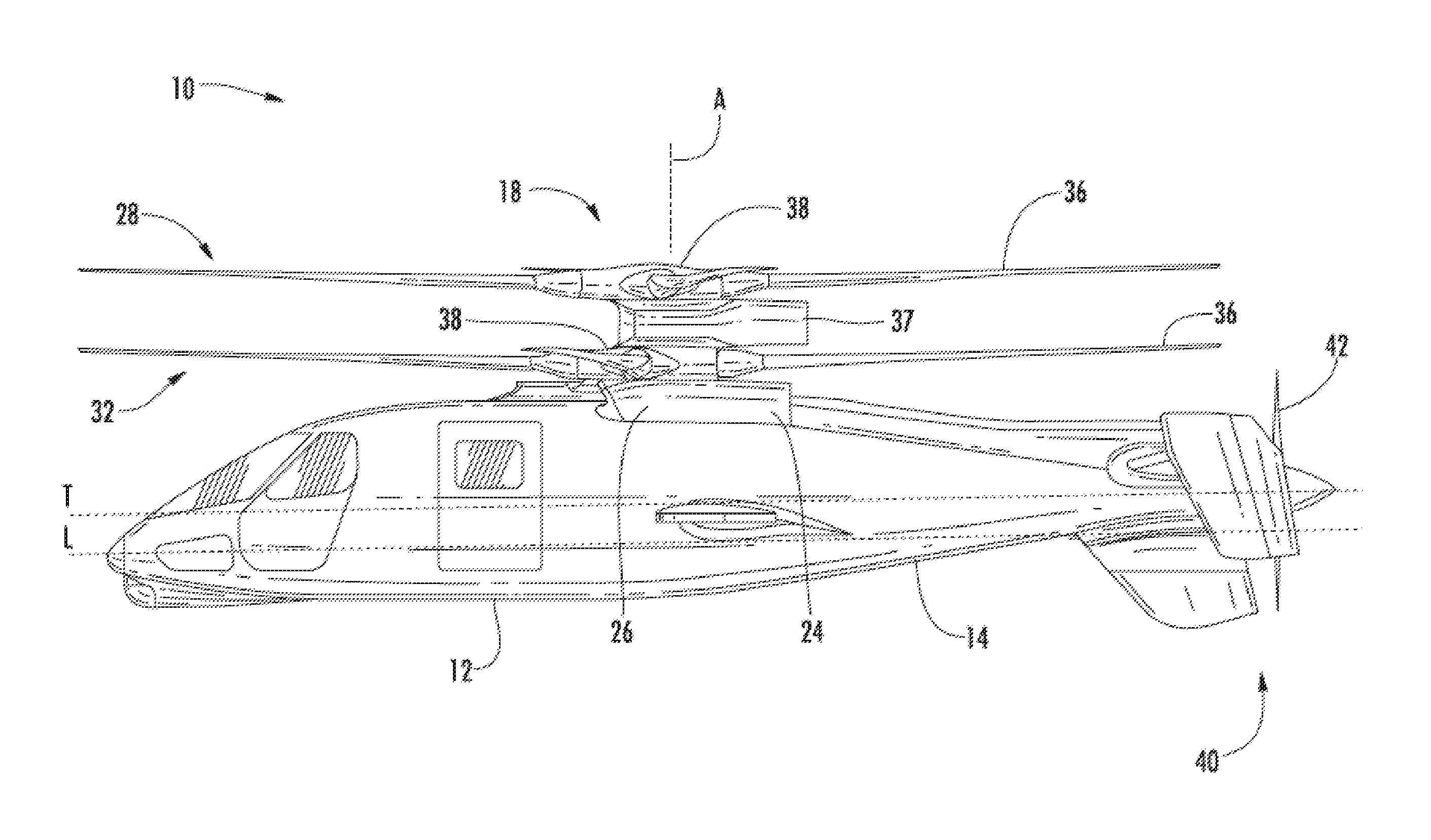
FIG. 1 depicts a rotary wing aircraft in an embodiment;
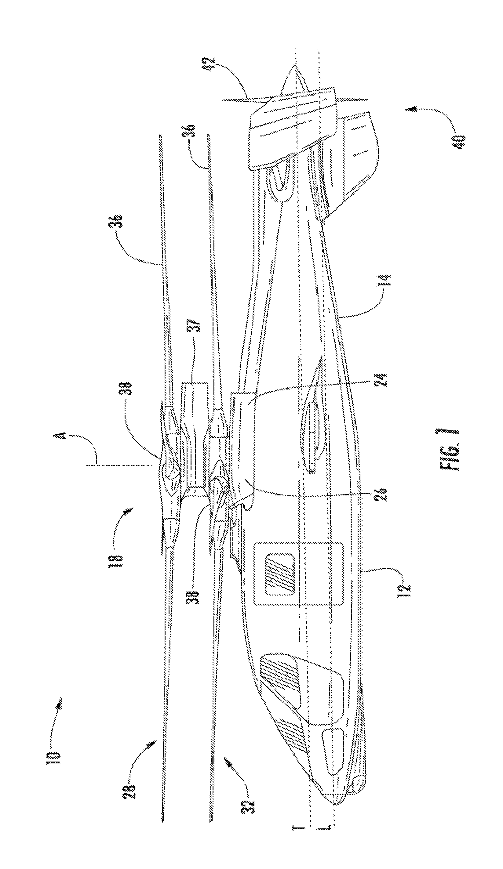
FIG. 2 is a perspective view of a rotary wing aircraft in an embodiment;
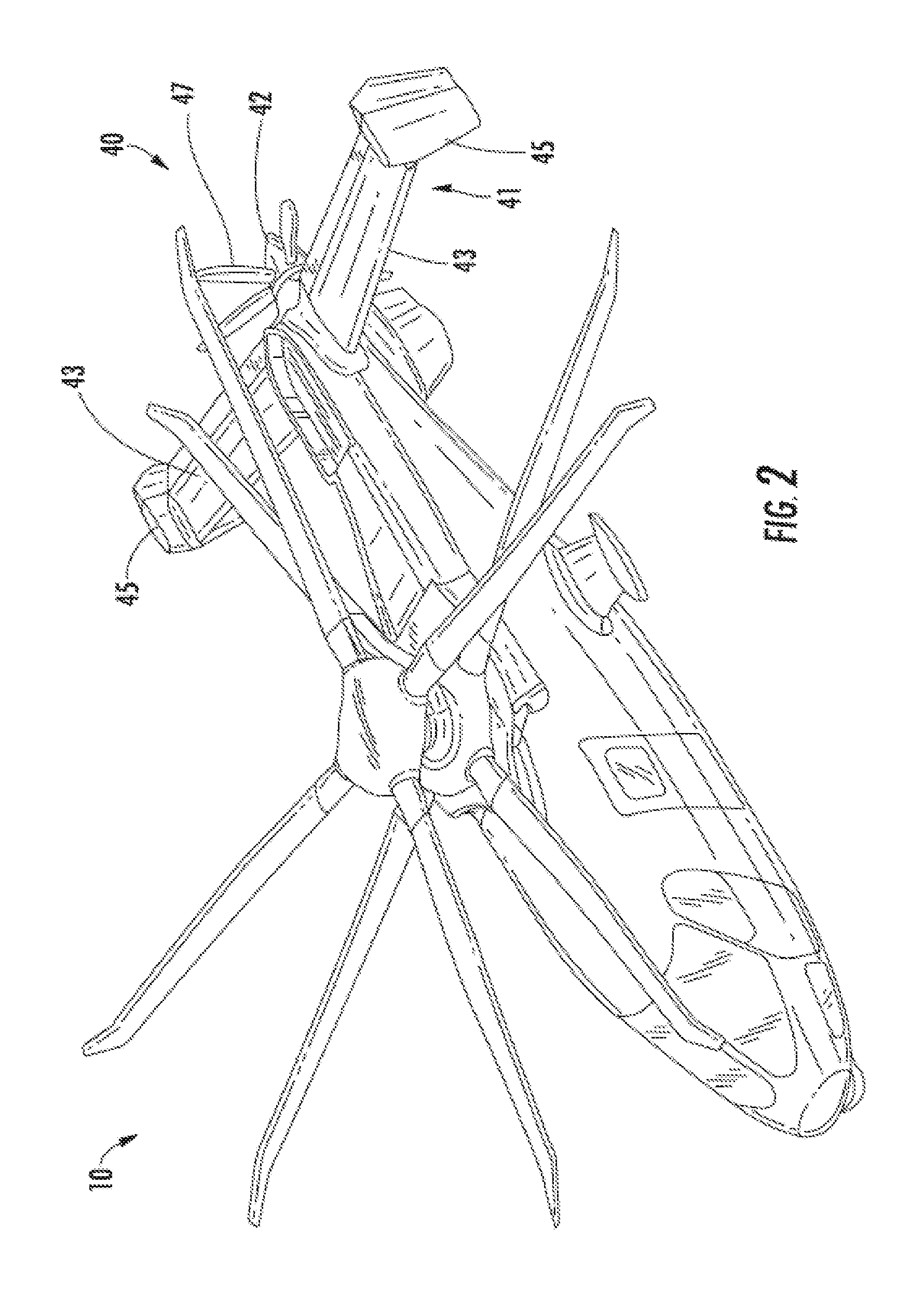
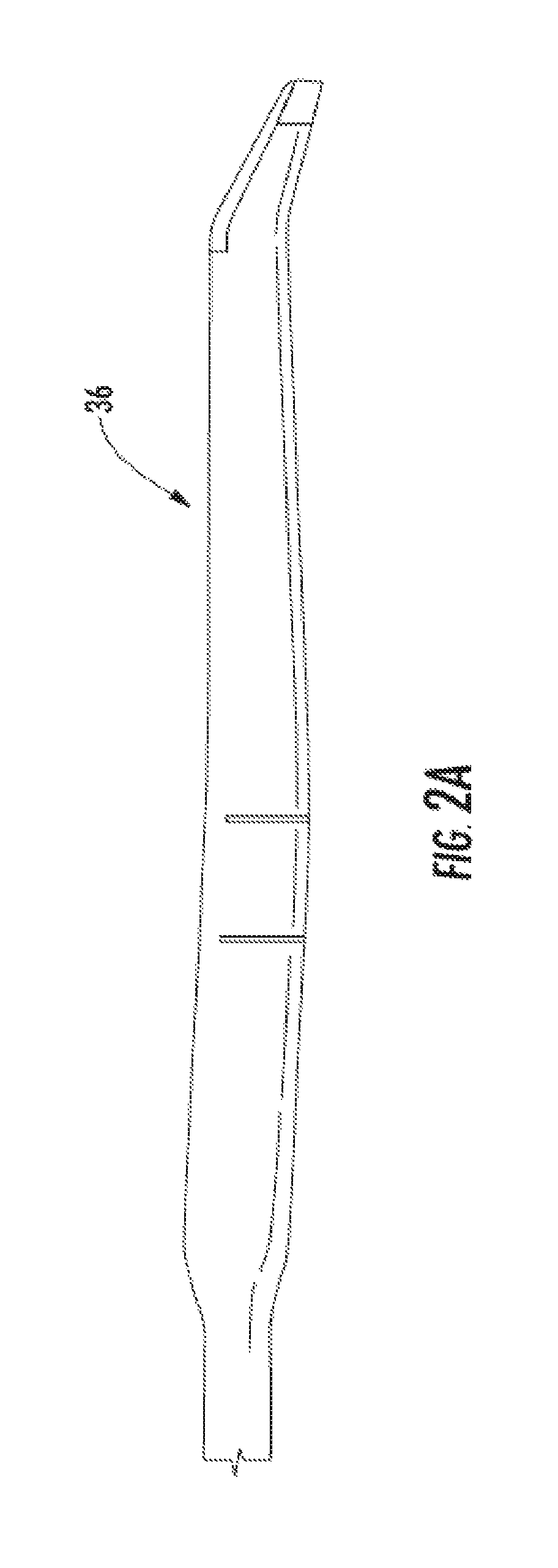
FIG. 2A depicts a planform of a rotor blade in an embodiment;
FIG. 3 is a perspective view of a gear train for a rotary wing aircraft in an embodiment;
FIGS. 3A and 3B depict power distribution in the gear box in hover and cruise modes in embodiments;
FIG. 3C depicts plots of percentage of power versus airspeed for a main rotor assembly and a propeller in an embodiment;
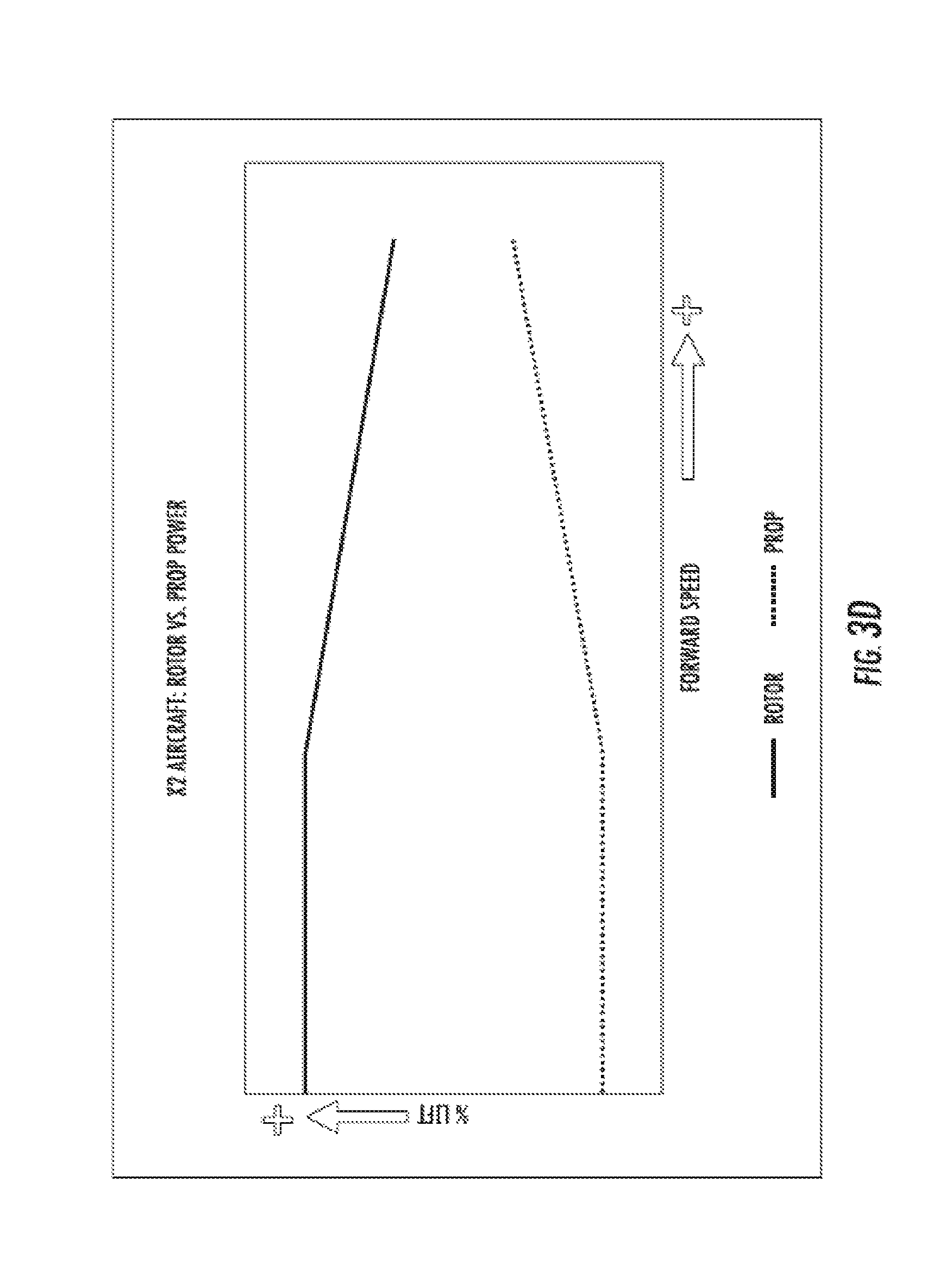
FIG. 3D depicts plots of percentage of lift versus airspeed for a main rotor assembly and a propeller in an embodiment;
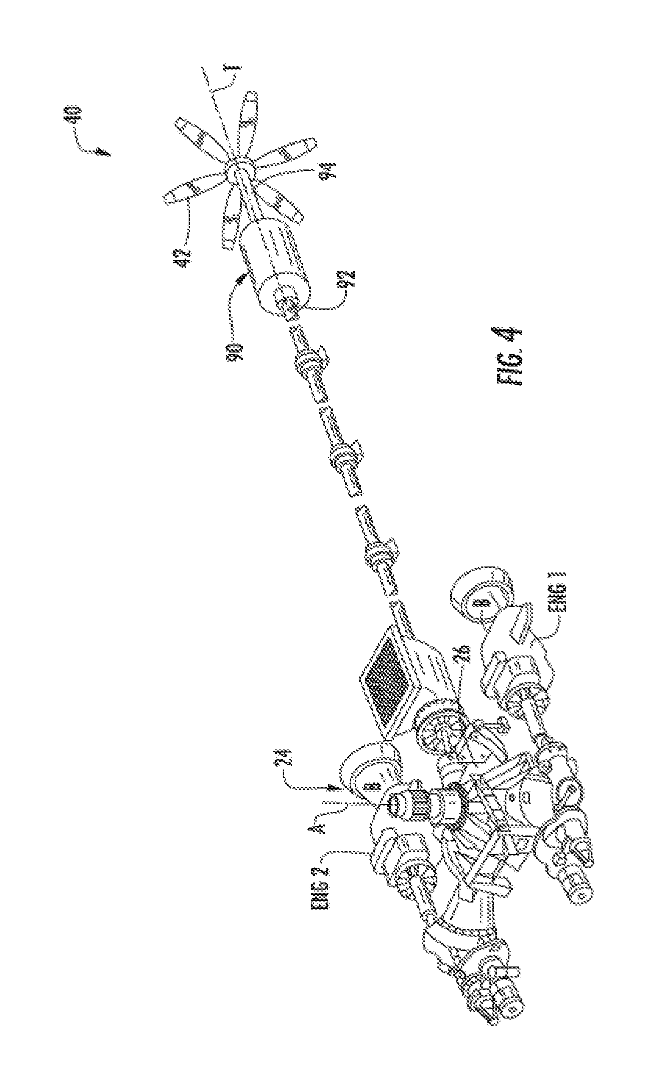
FIG. 4 is a perspective view of a gearbox and translational thrust system in an embodiment;
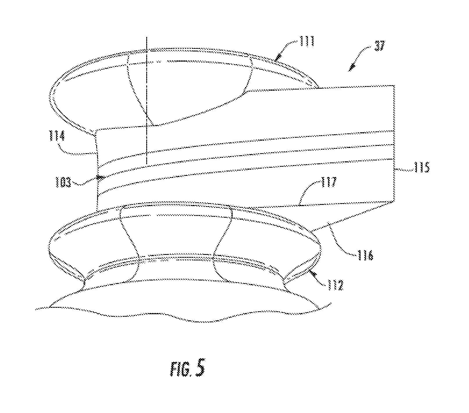
FIG. 5 is a perspective view of a rotor hub fairing in an embodiment;
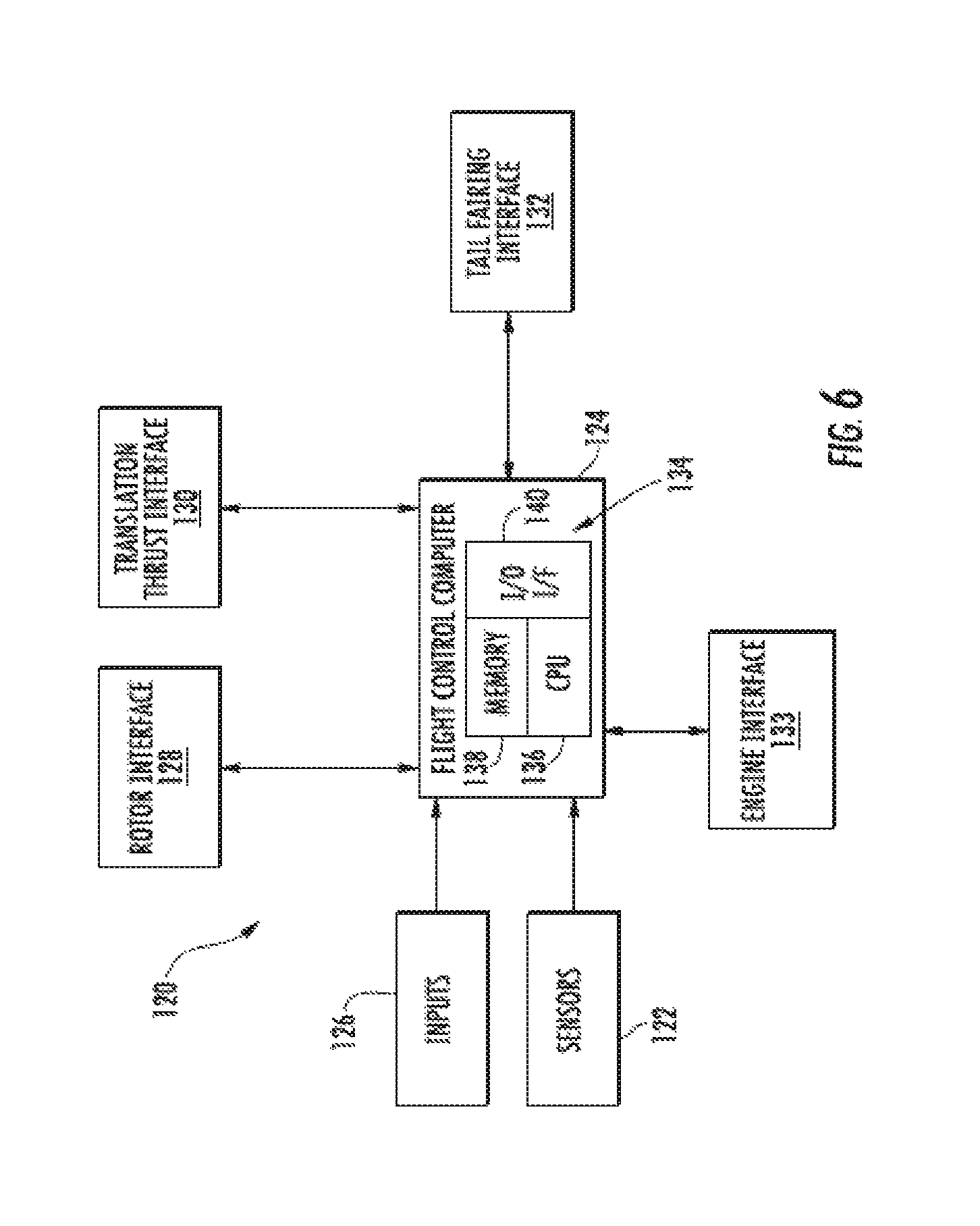
FIG. 6 depicts a flight control system in an embodiment;
FIG. 6A depicts a blade proximity detection system in an embodiment;
FIG. 7 depicts a flight maneuver in an embodiment;
FIG. 8 depicts front, side and top views of an embodiment of an aircraft;
FIG. 9 depicts a schematic of an embodiment of an active vibration control (AVC) system;
FIGS. 10 and 11 illustrate force vectors in exemplary hover states; and;
FIG. 12 illustrates operation of a system for control of main rotor rotational speed (N.sub.r).
DETAILED DESCRIPTION
FIG. 1 depicts an exemplary embodiment of a rotary wing, vertical takeoff and land (VTOL) aircraft 10. The aircraft 10 includes an airframe 12 with an extending tail 14. A dual, counter rotating, coaxial main rotor assembly 18 is located at the airframe 12 and rotates about a main rotor axis, A. In an exemplary embodiment, the airframe 12 includes two seats for flight crew (e.g., pilot and co-pilot) and six seats for passengers. The main rotor assembly 18 is driven by a power source, for example, one or more engines 24 via a gearbox 26. The main rotor assembly 18 includes an upper rotor assembly 28 driven in a first direction (e.g., counter-clockwise) about the main rotor axis, A, and a lower rotor assembly 32 driven in a second direction (e.g., clockwise) about the main rotor axis, A, opposite to the first direction (i.e., counter rotating rotors). Each of the upper rotor assembly 28 and the lower rotor assembly 32 includes a plurality of rotor blades 36 secured to a rotor hub 38. In some embodiments, the aircraft 10 further includes a translational thrust system 40 located at the extending tail 14 to provide translational thrust (forward or rearward) for aircraft 10.
Any number of blades 36 may be used with the rotor assembly 18. FIG. 2A depicts a planform of a rotor blade 36 in an exemplary embodiment. The rotor assembly 18 includes a rotor hub fairing 37 generally located between and around the upper and lower rotor assemblies such that the rotor hubs 38 are at least partially contained therein. The rotor hub fairing 37 provides drag reduction. Rotor blades 36 are connected to the upper and lower rotor hubs 38 in a hingeless manner, also referred to as a rigid rotor system. Although a particular aircraft configuration is illustrated in this non-limiting embodiment, other rotary-wing aircraft will also benefit from embodiments of the invention. Although, the dual rotor system is depicted as coaxial, embodiments include dual rotor aircraft having non-coaxial rotors.
The translational thrust system 40 includes a propeller 42 connected to and driven by the engine 24 via the gearbox 26. The translational thrust system 40 may be mounted to the rear of the airframe 12 with a translational thrust axis, T, oriented substantially horizontal and parallel to the aircraft longitudinal axis, L, to provide thrust for high-speed flight. The translational thrust axis, T, corresponds to the axis of rotation of propeller 42. While shown in the context of a pusher-prop configuration, it is understood that the propeller 42 could also be more conventional puller prop or could be variably facing so as to provide yaw control in addition to or instead of translational thrust. It should be understood that any such system or other translational thrust systems may alternatively or additionally be utilized. Alternative translational thrust systems may include different propulsion forms, such as a jet engine.
Referring to FIG. 2, translational thrust system 40 includes a propeller 42 and is positioned at a tail section 41 of the aircraft 10. Propeller 42 includes a plurality of blades 47. In exemplary embodiments, the pitch of propeller blades 47 may be altered to change the direction of thrust (e.g., forward or rearward). The tail section 41 includes active elevators 43 and active rudders 45 as controllable surfaces.
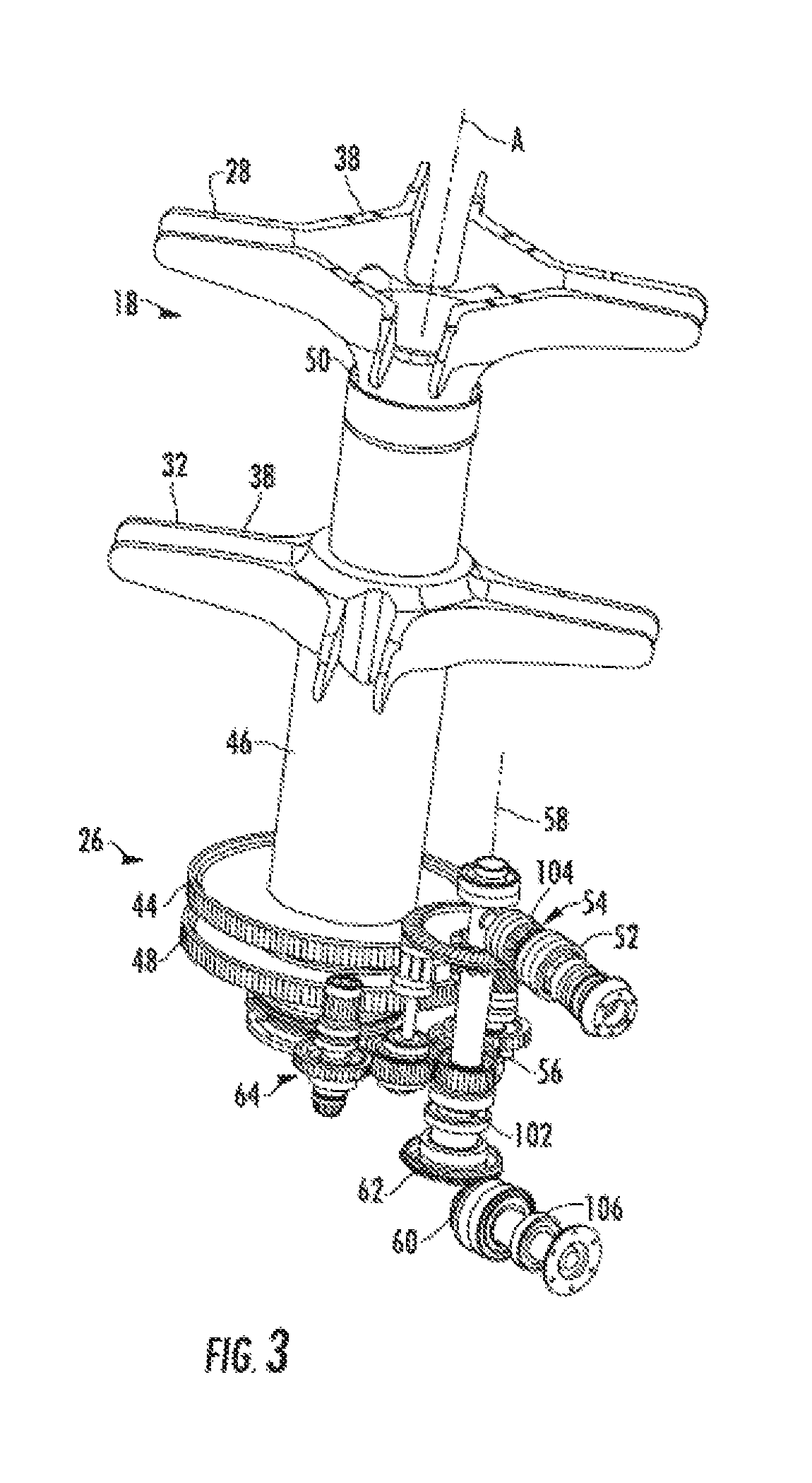
Shown in FIG. 3 is a perspective view of portions of main rotor assembly 18 and gearbox 26. The gearbox 26 includes an upper bull gear 44 rotates about the main rotor axis, A, and connected to the lower rotor assembly 32 via a lower rotor shaft 46 extending along the main rotor axis, A. A lower bull gear 48 rotates about the main rotor axis, A, and is connected to the upper rotor assembly 28 via an upper rotor shaft 50 extending along the main rotor axis, A, and through an interior of the lower rotor shaft 46. Torque and rotational speed are provided to the gearbox 26 via input shaft 52 that transmits the torque and rotational speed from the engine(s) 24 to an input bevel gear 54 disposed at an input bevel shaft 56 of the gearbox 26 via an input bevel pinion 104. In some embodiments, the input bevel shaft 56 rotates about an input bevel shaft axis 58 parallel to the main rotor axis A. The propeller 42 is driven by a propeller output shaft 106 driven by a propeller output gear 62 disposed at a quill shaft 102, or an extension of input bevel shaft 56. Transfer from the propeller output gear 62 is achieved via connection with a propeller output pinion 60 at the propeller output shaft 106. To transfer torque from the input bevel shaft 56 to the lower rotor assembly 32 and the upper rotor assembly 30, the gearbox 26 includes a torque split gear reduction stage 64. The torque split gear reduction stage 64 splits torque from the input shaft 52 and applies the divided torque to bull gears 44 and 48, respectively. While shown with the propeller output shaft 106 driven by the propeller output gear 62, it is understood that such elements could be removed where the propeller 42 is not used or is separately driven.
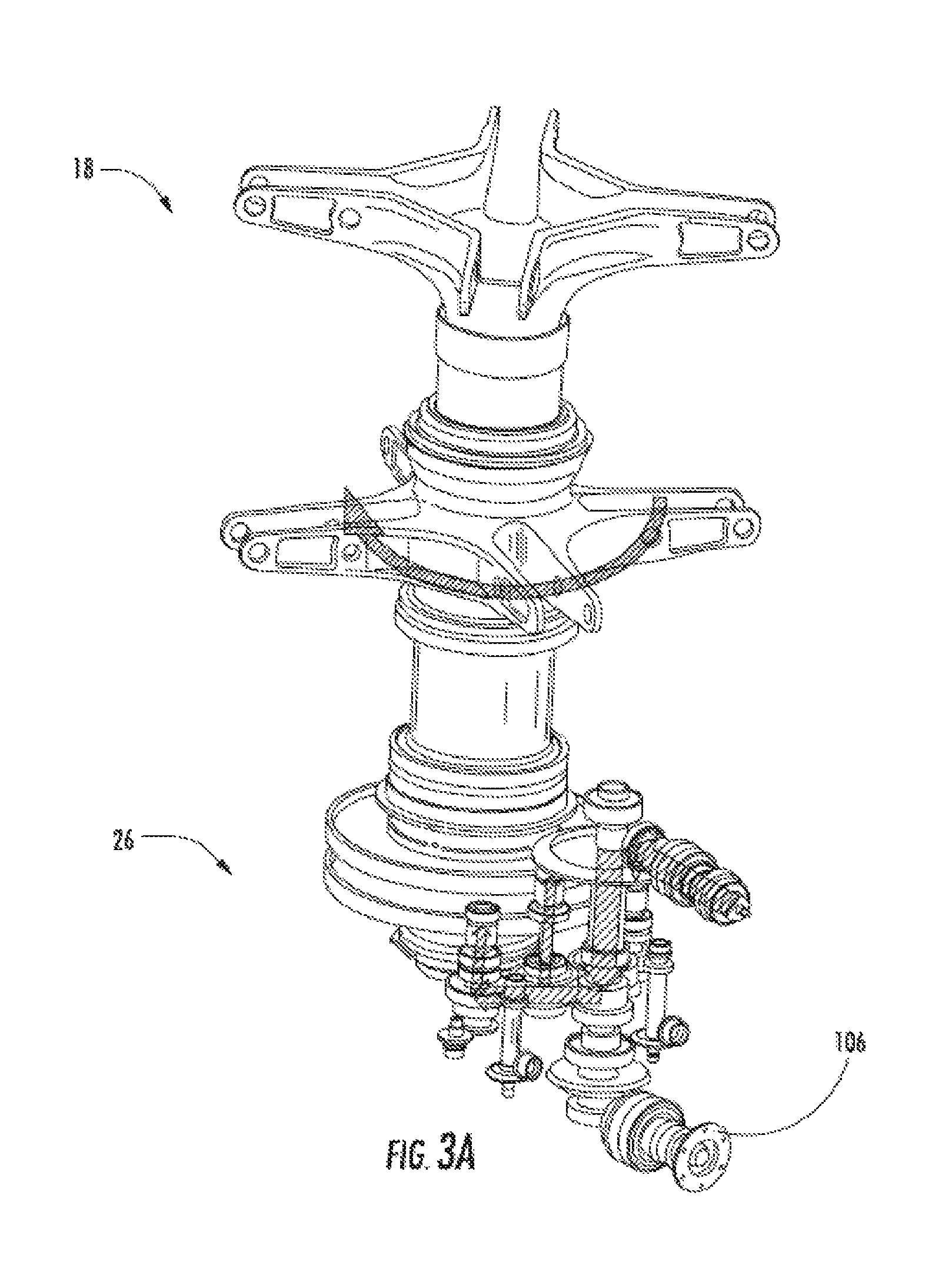
FIG. 3A illustrates power distribution through gearbox 26 to main rotor assembly 18 and propeller output shaft 106 during hover mode. In hover, power flows to torque split section to drive main rotor assembly 18. The propeller output shaft 106 spins at all times to drive features on propeller box while propeller 42 is unclutched. During hover mode, the majority of power flows to the main rotor assembly 18.
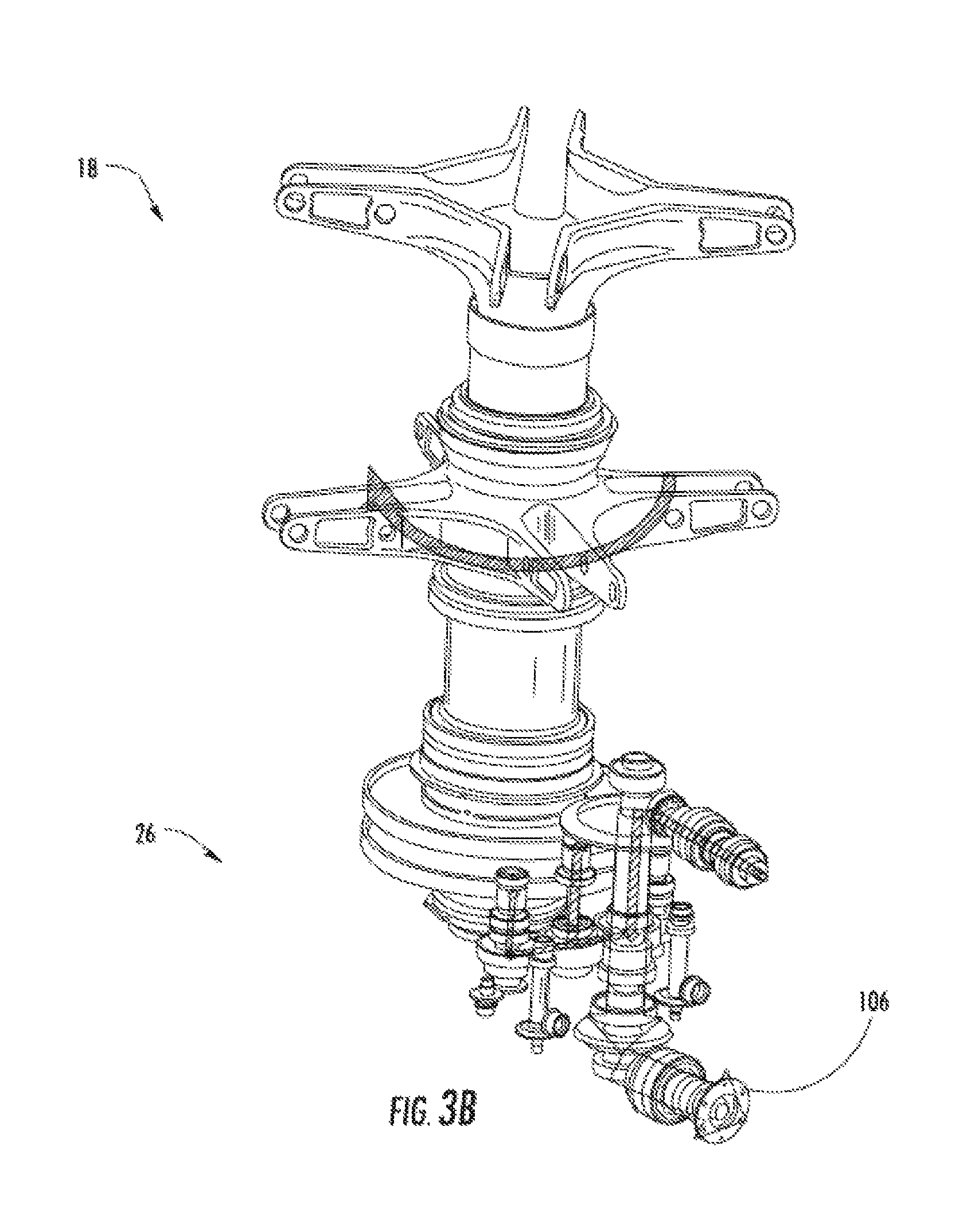
FIG. 3B illustrates power distribution through gearbox 26 to main rotor assembly 18 and propeller output shaft 106 during cruise mode. In high speed cruise, the majority of power flows to the propeller output shaft 106 while the main rotor assembly 18 is operating near an autorotative state.
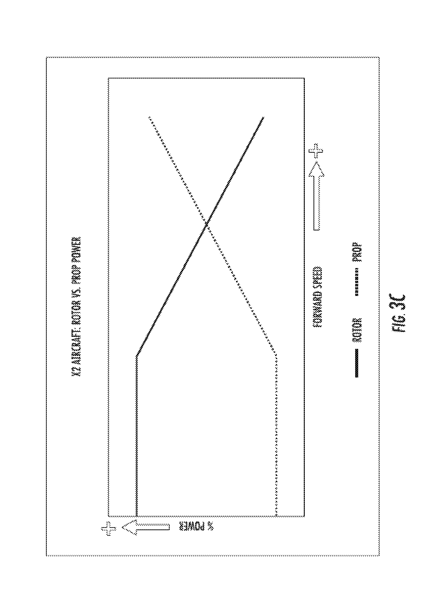
FIG. 3C depicts a plot of percentage of power versus airspeed for the main rotor assembly 18 and the propeller 42. The power between the main rotor assembly 18 and the propeller 42 is inversely proportional to air speed, once the aircraft reaches a propeller engagement speed. For example, at low airspeeds (e.g. below 100 kts), power is 100% used by the main rotor assembly 18. At the transition speed where the propeller 42 engages, the propeller 42 begins to use aircraft power. As airspeed increases, the main rotor assembly 18 power decreases and the propeller 42 power increases.
FIG. 3D depicts plots of percentage of lift versus airspeed for the main rotor assembly 18 and the propeller 42 in an exemplary embodiment. When aircraft 10 is flown in a nose up orientation, lift may be provided from the propeller 42. At low airspeeds (e.g. below 100 kts), lift is 100% provided by the main rotor assembly 18. At the transition speed where the propeller 42 engages, the propeller 42 begins to provide lift. As airspeed increases, the main rotor assembly 18 lift decreases and the propeller 42 lift increases.
Referring to FIG. 4, the main rotor assembly 18 is driven about the axis of rotation, A, through a main gearbox (MGB) 26 by a multi-engine powerplant system 24, having two engine packages ENG1, ENG2 in the example in FIG. 4. Although FIG. 4 depicts two engines 24, it is understood that aircraft 10 may use a single engine 24. The multi-engine powerplant system 24 generates power available for flight operations and couples such power to the main rotor assembly 18 and the translational thrust system 40 through the MGB 26. The MGB 26 may be interposed between the powerplant system 24, the main rotor assembly 18 and the translational thrust system 40.
A portion of the drive system downstream of the MGB 26 includes a combined gearbox 90 (also referred to as a clutch). The combined gearbox 90 selectively operates as a clutch and a brake for operation of the translational thrust system 40 with the MGB 26. The combined gearbox 90 also operates to provide a rotor brake function for the main rotor assembly 18.
The combined gearbox 90 generally includes an input 92 and an output 94 generally defined along an axis parallel to rotational axis, T. The input 92 is generally upstream of the combined gearbox 90 relative the MGB 26 and the output 94 is downstream of the combined gearbox 90 and upstream of the pusher propeller system 40 (FIG. 2). The combined gearbox 90 may be categorized by the technique used to disengage-engage (e.g., clutch) or stop (e.g., brake) the load such as friction, electromagnetic, mechanical lockup, etc., and by the method used to actuate such as mechanical, electric, pneumatic, hydraulic, self-activating, etc. It should be understood that various combined gearbox 90 systems may be utilized to include but not to be limited to mechanical, electrically, hydraulic and various combinations thereof.
Referring to FIG. 5, an exemplary rotor hub fairing 37 is shown. Rotor hub fairing 37 is illustrated having generally elliptical, in cross-section, upper and lower hub fairings 111 and 112, and an airfoil-type shape (in horizontal cross-section) for the shaft fairing 103. The airfoil shape of the shaft fairing 103 includes a leading edge 114, and a trailing edge 115 aft of the upper and lower fairings 111, 112. The airfoil shape of the shaft fairing 103 additionally includes a chord (not shown) that connects the leading and trailing edges 114, 115 of the airfoil. In one embodiment, the airfoil shape, including the upper surface 116 and the lower surface 117, is symmetrical about a plane extending along the length of the shaft fairing 103 and containing the axis of rotation, A. In other embodiments, the shaft fairing 103 may be a partial airfoil shape or another shape to reduce drag. As noted above, the upper and lower rotor hubs 38 may be positioned, at least partially, in the upper and lower fairings 111, 112.
Portions of the aircraft 10 are controlled by a flight control system 120 illustrated in FIG. 6. In one embodiment, the flight control system 120 is a fly-by-wire (FBW) control system. In a FBW control system there is no direct mechanical coupling between a pilot's controls and movable components of aircraft 10. Instead of using mechanical linkages, a FBW control system includes a plurality of sensors 122 which can sense the position of controlled elements and generate electrical signals proportional to the sensed position. The sensors 122 may also be used directly and indirectly to provide a variety of aircraft state data to a flight control computer (FCC) 124. The FCC 124 may also receive inputs 126 as control commands from various sources. For instance, the inputs 126 can be pilot inputs, auto-pilot inputs, navigation system based inputs, or any control inputs from one or more control loops executed by the FCC 124 or other subsystems. In response to inputs from the sensors 122 and inputs 126, the FCC 124 transmits signals to various subsystems of the aircraft 10.
Flight control system 120 may include a rotor interface 128 configured to receive commands from the FCC 124 and control one or more actuators, such as a mechanical-hydraulic or electric actuators, for the upper rotor assembly 28 and lower rotor assembly 32. In an embodiment, inputs 126 including cyclic, collective, pitch rate, and throttle commands that may result in the rotor interface 128 driving the one or more actuators to adjust upper and lower swashplate assemblies (not depicted) for pitch control of the upper rotor assembly 28 and lower rotor assembly 32. Alternatively, pitch control can be performed without a swashplate assemblies using individual blade control (IBC) in the upper rotor assembly 28 and lower rotor assembly 32. The rotor interface 128 can manipulate the upper rotor assembly 28 and lower rotor assembly 32 independently. This allows different collective and cyclic commands to be provided to the upper rotor assembly 28 and lower rotor assembly 32.
Flight control system 120 may include a translational thrust interface 130 configured to receive commands from the FCC 124 to control one or more actuators, such as a mechanical-hydraulic or electric actuators, for the control of the translational thrust system 40. In an embodiment, inputs 126 may result in the translational thrust interface 130 controlling speed of propeller 42, altering the pitch of propeller blades 47 (e.g., forward or rearward thrust), altering the direction of rotation of propeller 42, controlling gearbox 90 to employ a clutch to engage or disengage the propeller 42, etc.
Flight control system 120 may include a tail fairing interface 132. The tail fairing interface 132 is configured to receive commands from the FCC 124 to control one or more actuators, such as a mechanical-hydraulic or electric actuators, for the active elevator 43 and/or active rudders 45 of FIG. 2. In an embodiment, inputs 126 include an elevator pitch rate command for the tail fairing interface 132 to drive the one or more actuators for pitch control of the active elevators 43 of FIG. 2. In an embodiment, inputs 126 include a rudder command for the tail fairing interface 132 to drive the one or more actuators for positional control of the active rudders 45 of FIG. 2.
Flight control system 120 may include an engine interface 133. The engine interface 133 is configured to receive commands from the FCC 124 to control engine(s) 24. In an embodiment, inputs 126 include a throttle command from the pilot to adjust the RPM of engine(s) 24. FCC 124 may also send commands to engine interface 133 to control the engine(s) in certain predefined operating modes (e.g., quiet mode).
The FCC 124 includes a processing system 134 that applies models and control laws to augment commands based on aircraft state data. The processing system 134 includes processing circuitry 136, memory 138, and an input/output (I/O) interface 140. The processing circuitry 136 may be any type or combination of computer processors, such as a microprocessor, microcontroller, digital signal processor, application specific integrated circuit, programmable logic device, and/or field programmable gate array, and is generally referred to as central processing unit (CPU) 136. The memory 138 can include volatile and non-volatile memory, such as random access memory (RAM), read only memory (ROM), or other electronic, optical, magnetic, or any other computer readable storage medium onto which data and control logic as described herein are stored. Therefore, the memory 138 is a tangible storage medium where instructions executable by the processing circuitry 136 are embodied in a non-transitory form. The I/O interface 140 can include a variety of input interfaces, output interfaces, communication interfaces and support circuitry to acquire data from the sensors 122, inputs 126, and other sources (not depicted) and communicate with the rotor interface 128, the translation thrust interface 130, tail faring interface 132, engine interface 133, and other subsystems (not depicted).
In exemplary embodiments, the rotor interface 128, under control of the FCC 124, can control the upper rotor assembly 28 and lower rotor assembly 32 to pitch in different magnitudes and/or different directions at the same time. This includes differential collective, where the upper rotor assembly 28 has a collective pitch different than the collective pitch of the lower rotor assembly 32, in magnitude and/or direction. Differential pitch control also includes differential cyclic pitch control, where the upper rotor assembly 28 has a cyclic pitch different than the cyclic pitch of the lower rotor assembly 32, in magnitude, axis of orientation (e.g., longitudinal or lateral) and/or direction. The differential collective and the differential cyclic pitch control may be accomplished using independently controlled swashplates in the upper rotor assembly 28 and lower rotor assembly 32. Alternatively, differential collective and the differential cyclic pitch control may be accomplished using individual blade control in the upper rotor assembly 28 and lower rotor assembly 32.
The ability to independently control the pitch of the upper rotor assembly 28 and lower rotor assembly 32 allows the lower rotor assembly 32 to be adjusted due to its position beneath the upper rotor assembly 28. The lower rotor assembly 32 is located in the downwash of the upper rotor assembly 28. To accommodate for this, the lower rotor assembly 32 may have a collective pitch that differs from the collective pitch of the upper rotor assembly 28.
In the case of traditional helicopters, as the forward velocity of the aircraft increases, the velocity of the retreating blade relative to the airflow decreases. This causes a stall region to arise at the root of the retreating blade and expand towards to distal end of the blade as speed increases. As this stall region increases, the overall lift vector of the aircraft shifts from the center of the aircraft towards the advancing blade which is providing the majority of lift for the aircraft. This imbalance of lift creates an unstable rolling moment on the aircraft which is stabilized by a combination of reducing forward flight and blade flapping, which reduces overall aircraft lift. With a dual rotor aircraft, such as aircraft 10, the counter rotating rotor heads balance out the torque generated by each rotor head and also balances the lift generated by each advancing blade without the need for blade flapping or reducing the speed of the aircraft. This is made possible by the rigid rotor system. With two rigid rotors, the roll moments cancel at the main rotor shaft.
The use of upper rotor assembly 28 and lower rotor assembly 32 allows the pre-cone angle to be set on each individual rotor to reduce bending stress on the blades. In a hinged rotor design, the hinges will naturally go to an angle to reduce bending stress. On a rigid rotor aircraft, such as aircraft 10, there is no hinge, so the pre-cone angle is set to avoid the extra stress attributed to the bending moment. A useful pre-cone angle is one where the centrifugal force of the blade pulling out matches the lift of the blade up. Due to the independent nature of the upper rotor assembly 28 and lower rotor assembly 32, differential pre-cone is used in aircraft 10. Differential pre-cone refers to the fact that the upper rotor assembly 28 and lower rotor assembly 32 have different pre-cone angles. The different pre-cone angles for the upper rotor assembly 28 and lower rotor assembly 32 help maintain tip clearance. In an exemplary embodiment, the pre-angle on the upper rotor assembly 28 is about 3 degrees and the pre-cone angle on the lower rotor assembly 32 is about 2 degrees.
Aircraft 10 is operational in a variety of modes, including take-off, cruise, landing, etc. Cruise mode refers to generally horizontal flight. During cruise, aircraft 10 can reach speeds of above about 200 knots, with speed reaching up to about 250 knots. During cruise mode, the main rotor assembly 18 provides the majority of lift for the aircraft. In exemplary embodiments and flight modes, the main rotor assembly 18 provides greater than about 85% of the lift during cruise mode.
Aircraft 10 may assume various acoustic modes, depending on the flight state. FCC 124 may control RPM of engines 24, RPM of propeller 42, and clutch 90 to engage or disengage the propeller 42 to assume different noise levels. For example, at take-off noise may not be a concern, and there would be no changes in aircraft operation to adjust the noise level. As the aircraft approaches a target, it may be desirable to disengage the propeller 42 using clutch 90 and/or reduce RPM of engines 24 to reduce the noise produced by aircraft 10. The propeller 42 may be disengaged at various other flight states (e.g., high speed) to reduce noise. The RPM of the main rotor assembly 18 and RPM of propeller 42 may be independently controlled (e.g., through clutch 90 or FCC 124). This allows a variety of flight states to be achieved.
The pilot may enter separate commands to reduce aircraft noise, for example, disengaging the propeller 42, reducing engine RPM, and increasing collective pitch as separate inputs. Alternatively, the pilot may select a reduced noise mode (e.g., quiet mode) through single input, and the FCC 124 controls the various aircraft interfaces to achieve the desired mode. For example, the pilot may select a reduced noise mode at input 126, and the FCC automatically disengages the propeller 42, reduces the engine 24 RPM and/or increases collective pitch without further demand on the pilot.
The use of the translational thrust system 40 allows the aircraft 10 to move forward or rearward (depending on the pitch of the propeller blades) independent of the pitch attitude of the aircraft. Cyclic is used to adjust the pitch attitude (nose up, nose down or level) of the aircraft while the translational thrust system 40 provides forward and rearward thrust to, for example, balance the main rotor system forces to maintain position, or translate with a set body attitude.
The main rotor assembly 18 system and the translational thrust system 40 are connected through the main gear box 26. A gear ratio of main gear box 26 is selected so as to keep propeller 42 at a high efficiency and suitable noise level during cruise mode. The gear ratio of main gear box 26 dictates the ratio of the rotor speed of main rotor assembly 18 to propeller speed of propeller 42.
Embodiments of aircraft 10 provide the pilot with increased situational awareness by allowing the aircraft attitude (e.g., the angle of longitudinal axis, L, relative to horizontal) to be adjusted by cyclic pitch of the main rotor assembly 18 and the forward and rearward thrust to be controlled by the translational thrust system 40. This allows a variety of flight modes to be achieved, which allows the pilot to be more aware of their surroundings. Aircraft 10 can take off at a horizontal attitude (e.g., axis L is horizontal), which also may be referred to as vertical take-off. Aircraft 10 may also fly forward or cruise with the nose angled upwards, nose angled downwards or level. Aircraft 10 can hover with the nose angled upwards or downwards or level. FIGS. 10 and 11 illustrate force vectors from the main rotor assembly and propeller for hover nose up and hover nose down, respectively. Aircraft 10 can also land substantially parallel to a non-horizontal or sloped surface by adjusting the attitude of the aircraft using cyclic pitch of the main rotor assembly 18. The use of main rotor assembly 18 for aircraft attitude and the translational thrust system 40 for thrust allows aircraft 10 to assume a variety of trim states.
Embodiments provide independent control of the active elevators 43 and/or active rudders 45 as controllable surfaces in the tail section 41. The elevator surfaces 43 may be controlled independently by the FCC 124 through the tail faring interface 132. The rudder surfaces 45 may be controlled independently by the FCC 124 through the tail faring interface 132.
The configuration of aircraft 10 and the controlled afforded by FCC 124 allows aircraft 10 to provide a high bank angle capability at high speeds. For example, in an exemplary embodiment, aircraft 10 can achieve a bank angle of about 60 degrees at about 210 knots.
Aircraft 10 may make use of longitudinal lift offset in trim to compensate for rotor-on-rotor aerodynamic interaction between the upper rotor assembly 28 and lower rotor assembly 32. Aircraft 10 may adjust differential longitudinal cyclic as a function of operational states of the aircraft (e.g., take-off, cruise, land, etc.). Differential longitudinal cyclic refers to upper rotor assembly 28 and lower rotor assembly 32 having different cyclic pitch along the longitudinal axis of the aircraft. Differential longitudinal cyclic may also be used to generate yaw moments. Lift offset may be used to control aircraft, where lateral lift offset adjusts roll and longitudinal lift offset adjusts pitch.
FCC 124 may control RPM of engine(s) 24, RPM of propeller 42, and clutch 90 to engage or disengage the propeller 42 to assume different noise levels. For example, at take-off noise may not be a concern, and there would be no changes in aircraft operation to adjust the noise level. As the aircraft approaches a target, it may be desirable to disengage the propeller 42 using clutch 90 and/or reduce RPM of engines 24 to reduce the noise produced by aircraft 10. The propeller 42 may be disengaged at various other flight states (e.g., high speed) to reduce noise. The RPM of the main rotor assembly 18 and RPM of propeller 42 may be independently controlled (e.g., through clutch 90).
The pilot may enter separate commands to reduce aircraft noise, for example, disengaging the propeller 42 and reducing engine RPM as separate inputs. Alternatively, the pilot may select a reduced noise mode (e.g., quiet mode) through single input, and the FCC 124 controls the various aircraft interfaces to achieve the desired mode. For example, the pilot may select a reduced noise mode at input 126, and the FCC automatically disengages the propeller 42 and/or reduces the engine 24 RPM without further demand on the pilot.
Aircraft 10 provides the ability to approach a target and reverse thrust while maintaining an attitude directed at the target. FIG. 7 depicts aircraft 10 approaching a target 200. In a first state, 202, the aircraft 10 alters the pitch of blades 47 in propeller 42 to provide reverse thrust to bring the aircraft to a quick stop. At state 204, the main rotor assembly 18 and propeller 42 are controlled to pitch aircraft 10 towards target 200. At state 206, the propeller 42 is used to provide reverse thrust to move away from target 200 and climb, while still maintaining an attitude with the nose of aircraft 10 facing target 200.
The use of a dual rotor system and translational thrust allows aircraft 10 to eliminate the need for a variable angle between the main axis of rotation of the rotor system (e.g., axis A in FIG. 1) and aircraft longitudinal axis L. In conventional helicopters, the angle between the main axis of rotation of the rotor system and the aircraft longitudinal axis L varies. This is due to the fact that conventional helicopters lack a translational thrust system 40 for use during cruise mode, or forward flight. In a conventional helicopter, forward flight is provided through cyclic pitch, which causes the aircraft to point nose down. As this nose down orientation is undesirable beyond a certain angle, the angle between the main axis of rotation of the rotor system and the aircraft longitudinal axis L is adjusted to bring the nose upwards, while still in forward flight.
By contrast, aircraft 10, with translational thrust system 40, does not need to adjust the angle between the main axis of rotation of the rotor system (e.g., axis A in FIG. 1) and aircraft longitudinal axis L. The angle between the main axis of rotation of the rotor system (e.g., axis A in FIG. 1) and aircraft longitudinal axis L for aircraft 10 remains fixed during all flight modes, including take-off, cruise, landing, etc.
As shown in FIG. 1, the rotor assembly 18 includes a rotor hub fairing 37 generally located between and around the upper and lower rotor assemblies such that the rotor hubs 38 are at least partially contained therein. The rotor hub fairing 37 provides drag reduction. Referring to FIG. 5, an exemplary rotor hub fairing 37 is shown. Rotor hub fairing 37 is illustrated having generally elliptical, in cross-section, upper and lower hub fairings 111 and 112, and an airfoil-type shape (in horizontal cross-section) for the shaft fairing 103. The airfoil shape of the shaft fairing 103 includes a leading edge 114, and a trailing edge 115 aft of the upper and lower fairings 111, 112. The airfoil shape of the shaft fairing 103 additionally includes a chord (not shown) that connects the leading and trailing edges 114, 115 of the airfoil. In one embodiment, the airfoil shape, including the upper surface 116 and the lower surface 117, is symmetrical about a plane extending along the length of the shaft fairing 103 and containing the axis of rotation, A. As noted above, the upper and lower rotor hubs 38 may be positioned, at least partially, in the upper and lower fairings 111, 112.
The rotor hub fairing 37 is a sealed fairing, meaning there are few or no passages for air to travel through the interior of the rotor hub fairing 37. In conventional designs, control devices such as pushrods, are exposed near the rotor hubs. The surfaces of these components increase drag on the rotor assembly. The air gaps between various rotor structures (e.g., pushrods and main rotor shaft) also form areas of drag. The sealed rotor hub fairing 37 eliminates air pathways through the rotor hub structure, and eliminates drag associated with such air paths.
Another feature to reduce drag on the rotor hub is positioning control rods, such as push rods for rotor control, internal to the main rotor shaft. Referring to FIG. 3, pushrods for swashplates in the upper rotor assembly 28 and lower rotor assembly 32 are located internal to the lower rotor shaft 46 and upper rotor shaft 50. This prevents the pushrods from being exposed and increasing drag on the rotor hub. The use of a rigid rotor system aids in sealing the rotor hub faring 37.
In an exemplary embodiment, the distance between the hub of the upper rotor assembly 28 and the hub of the lower rotor assembly 32 ranges from about 2 feet to about 2.5 feet. In another exemplary embodiment, the distance between the hub of the upper rotor assembly 28 and the hub of the lower rotor assembly 32 ranges from about 2.1 feet to about 2.4 feet. In another exemplary embodiment, the distance between the hub of the upper rotor assembly 28 and the hub of the lower rotor assembly 32 is about 2.29 feet (0.7 meters).
Aircraft 10 may employ an active vibration control (AVC) system to reduce vibration in the airframe 12. The use of a dual rotor, rigid rotor system tends to produce significant vibration in the airframe 12 and its systems. FIG. 9 depicts an AVC system in an exemplary embodiment. An AVC controller 300 executes an AVC control process to reduce vibration in aircraft 10. AVC controller 300 may be implemented as part of flight control system 120, executed by FCC 124, or may be a separate controller. One or more sensors 302 are located in aircraft 10 to detect vibration. Sensors may be located in a wide variety of positions, including airframe 12, gearbox 26, tail section 14, on main rotor assembly 18, cockpit, etc. It is understood that these locations are exemplary, and the AVC sensors 302 may be located in any position. AVC actuators 304 generate a force to dampen vibration in aircraft 10, as known in the art. AVC actuators 304 may be located in any position in the aircraft.
In operation, AVC controller 300 receives vibration signals from the AVC sensors 302. AVC controller 300 provides control signals to the AVC actuators 304 to generate forces to reduce the vibration sensed by the AVC sensors 302. Control signals to the AVC actuators 304 may vary in magnitude and frequency to cancel vibrations in aircraft 10. In an exemplary embodiment, AVC controller 300 operates in a feedback mode, where the control signals to AVC actuators 304 are adjusted in response to measured vibration from AVC sensors 302.
In an alternate embodiment, AVC controller 300 does not actively measure vibration through AVC sensors 302. Rather, the AVC controller 300 obtains the rotor speed (e.g., through an RPM signal) and applies a control signal to the AVC actuators 304, in an open loop control mode.
The use of independently controlled upper rotor assembly 28 and the lower rotor assembly 32, along with other control surfaces, provides the ability to control yaw using a variety of elements. For example, below a first speed, (e.g., 40 knots), the FCC 124 uses differential collective pitch for yaw control. Above the first speed but below a second speed (e.g., 80 knots), a mix of differential collective and differential cyclic may be used to control yaw. The differential cyclic may be applied along the longitudinal and/or lateral axes of the aircraft. Further, wind direction may be measured by a sensor 122 and used to adjust the differential cyclic about the longitudinal and/or lateral axes. Above the second speed (e.g., 80 knots), the active rudders 45 are used as controllable surfaces to control yaw. The FCC 124 provides commands to the tail fairing interface 132 to control the rudders 45 to adjust yaw.
The use of active elevator 43, with independent control of a left elevator section and a right elevator section, provides for improved stability control. Flight control system 120 performs mixing of collective pitch of main rotor assembly 18 and an angle of elevator 43 to provide stability augmentation.
Embodiments may use wireless techniques to provide tip clearance measurements. FIG. 6A depicts a blade proximity monitoring system in an exemplary embodiment. At least one upper rotor blade and at least one lower rotor blade is equipped with at least one antenna 502. Antennas 502 may be electric field antennas or magnetic field antennas. Antennas 502 may be implemented using compact ferrite core or small diameter magnet wire in the form of coils around the blade spar or embedded in the plane of the blade skin. The antennas 502 interact through the near field effect.
An oscillator 504 sends an excitation signal (e.g., 40 KHz) to a first antenna 502L. It is understood that the excitation signal may be sent to a plurality of antennas in different blades, including multiple antennas in the same blade. As the blades cross, a second antenna, 502U, receives a signal emitted by the first antenna 502 L. An output level monitor 506 measures the magnitude of the excitation signal.
A blade proximity monitor 508 (e.g., a processor implemented controller) is mounted in the rotating system, e.g., in a rotor hub. This eliminates noise that may be introduced through a conventional slip ring used to convey signals from a rotating system to a stationary system. The blade proximity monitor 508 receives an output signal from the second antenna 502U and the magnitude of the excitation signal from the output level monitor 506. Output signal from the second antenna 502U may be amplified. The blade proximity monitor 508 also receives a RPM signal of the main rotor assembly 18 from a contactor 510. Based on the magnitude of the excitation signal applied to the first antenna 502L and the magnitude of the output signal from the second antenna 502U, blade proximity monitor 508 can detect the distance between the first antenna 502L and the second antenna 502U. This provides an indication of the distance between the rotor blades. The larger the magnitude of the output signal from second antenna 502U, the closer the blades.
The blade proximity monitor 508 may output the measured distance between the blades to a rotor track and balance unit 512. The blade proximity monitor 508 may output the measured distance between the blades to instrument system 514 and to a pilot display 516. If the measured distance goes below a threshold, then an alert may be generated to the pilot that the blades of the upper rotor assembly 32 and the lower rotor assembly 28 are too close to each other.
The use of a dual rotor, main rotor assembly 18 allows improvements in control of main rotor assembly 18. Flight control system 120 may apply different control envelopes to the upper rotor assembly 28 and the lower rotor assembly 32. Flight control system 120 may impose different control ranges the upper rotor assembly 28 and the lower rotor assembly 32 including control elements such as prioritization, gain vs. differential, collective versus cyclic, etc. The upper rotor assembly 28 and the lower rotor assembly 32 may be independently controlled through the use of separate upper and lower swashplates. Alternatively, the upper rotor assembly 28 and the lower rotor assembly 32 may be independently controller using individual blade control (IBC) techniques.
Aircraft 10 employs a fly-by-wire (FBW) control system to reduce pilot work load. In an exemplary embodiment, FCC 124 determines the aircraft airspeed based on one or more sensors 122. The FCC 124 then adjusts the collective pitch of the upper rotor assembly 28 and/or the lower rotor assembly 32 in response to the airspeed. FCC 124 may use a look up table that indexes airspeed to collective pitch. Alternatively, FCC 124 may use an algorithm to compute the collective pitch based on airspeed. As noted above, the collective pitch of upper rotor assembly 28 and the lower rotor assembly 32 may be the same or different.
Another feature to reduce pilot workload includes automatically adjusting the RPM and/or pitch of propeller 42 in response to a velocity or acceleration command from the pilot. Conventional systems would require the pilot to adjust propeller RPM and/or pitch through individual inputs. The flight control system 120 allows the pilot to enter a desired velocity or an acceleration, and the FCC 124 generates the proper commands to the translational thrust interface 130 to establish an RPM and/or pitch to meet the desired velocity or acceleration.
Referring now to FIG. 12, in exemplary embodiments, the flight control system 120 controls the rotational speed of the main rotor assembly 18. During cruise operation of the aircraft 10 at high airspeeds, in some embodiments greater than about 200 knots airspeed, the main rotor assembly 18 is slowed down (within practical constraints) and operated in a manner to maximize its efficiency, and propulsive force is provided by the propeller 42. Further, an engine controller of the flight control system 120 controls the rotational speed of the main rotor assembly 18 to prevent the tips of rotor blades 36 from exceeding a threshold rotor tip speed. In exemplary embodiments, the threshold rotor tip speed may be Mach 0.9. This threshold rotor tip speed would prevent the rotor blade tips from exceeding the speed of sound. The threshold rotor tip speed may vary, and may be set to limit drag on the rotor blades 36 to below a certain level. In one embodiment, the FCC 124 determines air temperature from sensors 122. FCC 124 may also determine prevailing wind speed and direction from sensors 122, as well as airspeed of the aircraft 10. The FCC 124 then computes the threshold rotor tip speed based on the speed of sound (e.g., Mach 1) at the sensed air temperature, airspeed and/or wind speed and direction. By way of example, the FCC 124 in FIG. 12 calculates the rotor tip speed using equation 1 below: Advancing blade tip Mach number=(Airspeed+main rotor rpm)/speed of sound at Outside Air Temperature Equation (1)
The FCC 124 may set the threshold to Mach 0.9, for example. FCC 124 then controls RPM of the main rotor assembly 18, by communication with the engine controller of the flight control system 120, to prevent the rotor blade tips from exceeding the threshold based on the calculated Advancing blade tip Mach number from Equation (1). In an exemplary embodiment, the FCC 124 maintains 85% of the nominal rotor RPM. FCC 124 may take into account airspeed and/or prevailing wind direction and speed in controlling the RPM of the main rotor assembly 18. The Mach 0.9 threshold is only one example, and other speed thresholds may be employed to achieve desired results (e.g., reduce drag).
In exemplary embodiments, active elevator 43 is configured and controlled to improve stability be compensating for forces such as propeller torque and/or rotor downwash. Elevator 43 includes a left elevator and a right elevator on opposite sides of the axis of rotation of the propeller 42. The left elevator and right elevator may be independently controlled to assume different positions. The tail fairing interface 132 is configured to receive commands from the FCC 124 to control one or more actuators, such as a mechanical-hydraulic or electric actuators, to position the left elevator and right elevator independently. This independent control of the left elevator and right elevator aids in compensating propeller torque and/or rotor downwash.
The left elevator and right elevator may also have different physical configurations to compensate for compensating propeller torque and/or rotor downwash. The left elevator and right elevator may be offset relative to each other along the longitudinal and/or lateral axes of aircraft 10. Further, the left elevator and right elevator may have different geometries where one of the left elevator and right elevator is larger than then other along the longitudinal and/or lateral axes of aircraft 10. The left elevator and right elevator may have differing aerodynamic surfaces (e.g., airfoils) as well.
The cockpit of aircraft includes a single, semi-active, collective input (e.g., stick) positioned between the two pilot seats.
Exemplary embodiments of aircraft 10 provide a much smaller footprint than existing aircraft. This makes aircraft 10 well suited for missions in confined terrain, urban settings, and shipboard operations. FIG. 8 presents front, side and top views of an exemplary aircraft. One feature contributing to the reduced footprint is the location of the main rotor shaft relative to the airframe 12. As shown in FIG. 1, the axis of rotation A, of the main rotor assembly 18, intersects longitudinal axis, L, along a span of axis L, extending from the nose of the aircraft to the tip of the hub of propeller 42. In an exemplary embodiment, the axis of rotation A is located at about a 44% station (STA) of the fuselage or airframe 12.
In an exemplary embodiment, there is about 5.2 inches from the main rotor pylon to the blade hub centerline. In an exemplary embodiment, there is about 0.7 inch hub clearance to the main rotor pylon. In an exemplary embodiment, the rotor blades 36 extend beyond the nose of the aircraft by about 13 inches (0.33 meters). In an exemplary embodiment, rotor blades 36 extend beyond the nose of the aircraft by about 6.9% of the blade span, which may be about 188''
The use of a rigid rotor system, along with the rotor shaft position (e.g., axis A) allows for much easier air-to-air refueling. The stiff rotor blades 36 ease air-to-air refueling by reducing blade flapping, which may result in a blade contacting a tanker fuel line during refueling.
Aircraft 10 provides an improved glide slope ratio of about 5-to-1 to about or 6-to-1. This is due to the propeller 42 taking energy out of the airstream, inputting energy into the gear box 26 to increase the speed of the main rotor assembly 18 during autorotation. As shown in FIGS. 3 and 4, the main gear box 26 interconnects the main rotor assembly 18 and propeller 42. During autorotation, the airflow rotates propeller 42, which will subsequently rotate the main rotor assembly 18 and thus increase lift. Propeller 42 also helps stabilize aircraft 10 during decent by acting like a parachute and a rudder, both slowing aircraft 10 and helping to direct aircraft 10 to maintain control. The ability to fly aircraft 10 in a nose down attitude also improves glide slope ratio.
In an exemplary embodiment, the distance between the hub of the upper rotor assembly 28 and the hub of the lower rotor assembly 32 ranges from about 2 feet to about 2.5 feet. In another exemplary embodiment, the distance between the hub of the upper rotor assembly 28 and the hub of the lower rotor assembly 32 ranges from about 2.1 feet to about 2.4 feet. In another exemplary embodiment, the distance between the hub of the upper rotor assembly 28 and the hub of the lower rotor assembly 32 is about 2.29 feet. In another exemplary embodiment, the distance between a midpoint of a blade in the upper rotor assembly 28 and a midpoint of a blade in the lower rotor assembly 32 is about 29.0 inches. In another exemplary embodiment, the distance between a tip of a blade in the upper rotor assembly 28 and a tip of a blade in the lower rotor assembly 32 is about 31.0 inches. In another exemplary embodiment, the distance between the hub of the upper rotor assembly 28 and the hub of the lower rotor assembly 32 is about 14% of the blade span, which may be about 188 inches.
While the present disclosure has been described in detail in connection with only a limited number of embodiments, it should be readily understood that the present disclosure is not limited to such disclosed embodiments. Rather, the present disclosure can be modified to incorporate any number of variations, alterations, substitutions or equivalent arrangements not heretofore described, but which are commensurate in scope. Additionally, while various embodiments have been described, it is to be understood that aspects of the present disclosure may include only some of the described embodiments. Accordingly, the present disclosure is not to be seen as limited by the foregoing description, but is only limited by the scope of the appended claims.
* * * * *
References
-
copters.com/mech/mr_semi.html
-
cavaltypilot.com/fm1-514/Ch2.htm
-
arc.aiaa.org/DOI:10.2514/1.C032941
-
aitforce-technology.com/projects/superhawk
-
hightech-edge.com/kikorsky-x2-raider-s-97-high-speed-military-helicopter/7936
-
scribb.com/doc/159484608/Aerodynamics-Clancy#scribd
-
cfidarren.com/hlesson5.htm
-
sikorskyarchives.com/S-69%20
-
youtube.com/watch?v=TRv5OxPFeQo
-
richardcyoung.com/terrorism/weapons/x2-raider-prototype
-
popularmechanics.com/flight/a10616/the-rise-of-radical-new-rotorcraft-16850989
D00000
D00001
D00002
D00003
D00004
D00005
D00006
D00007
D00008
D00009
D00010
D00011
D00012
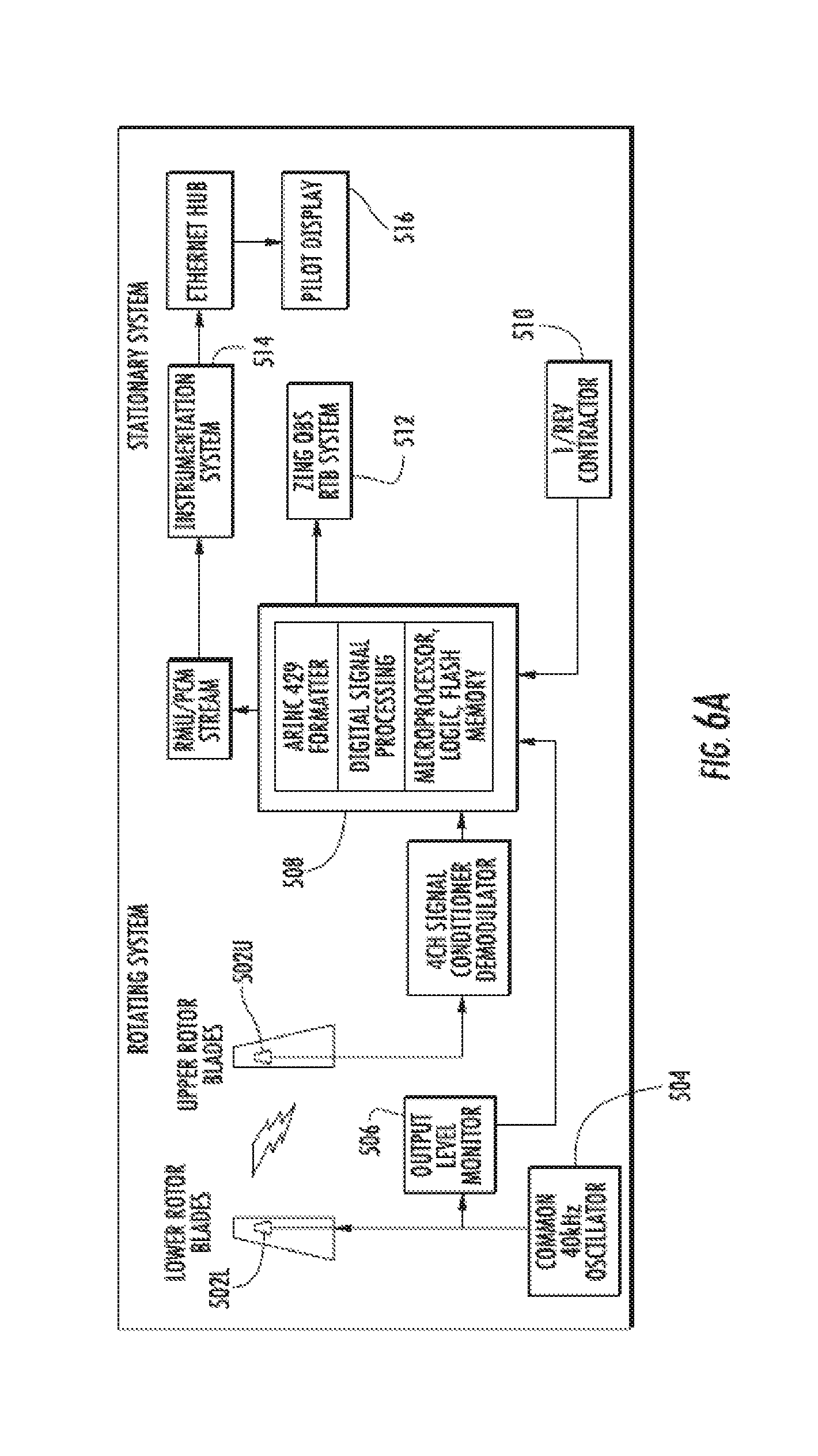
D00013
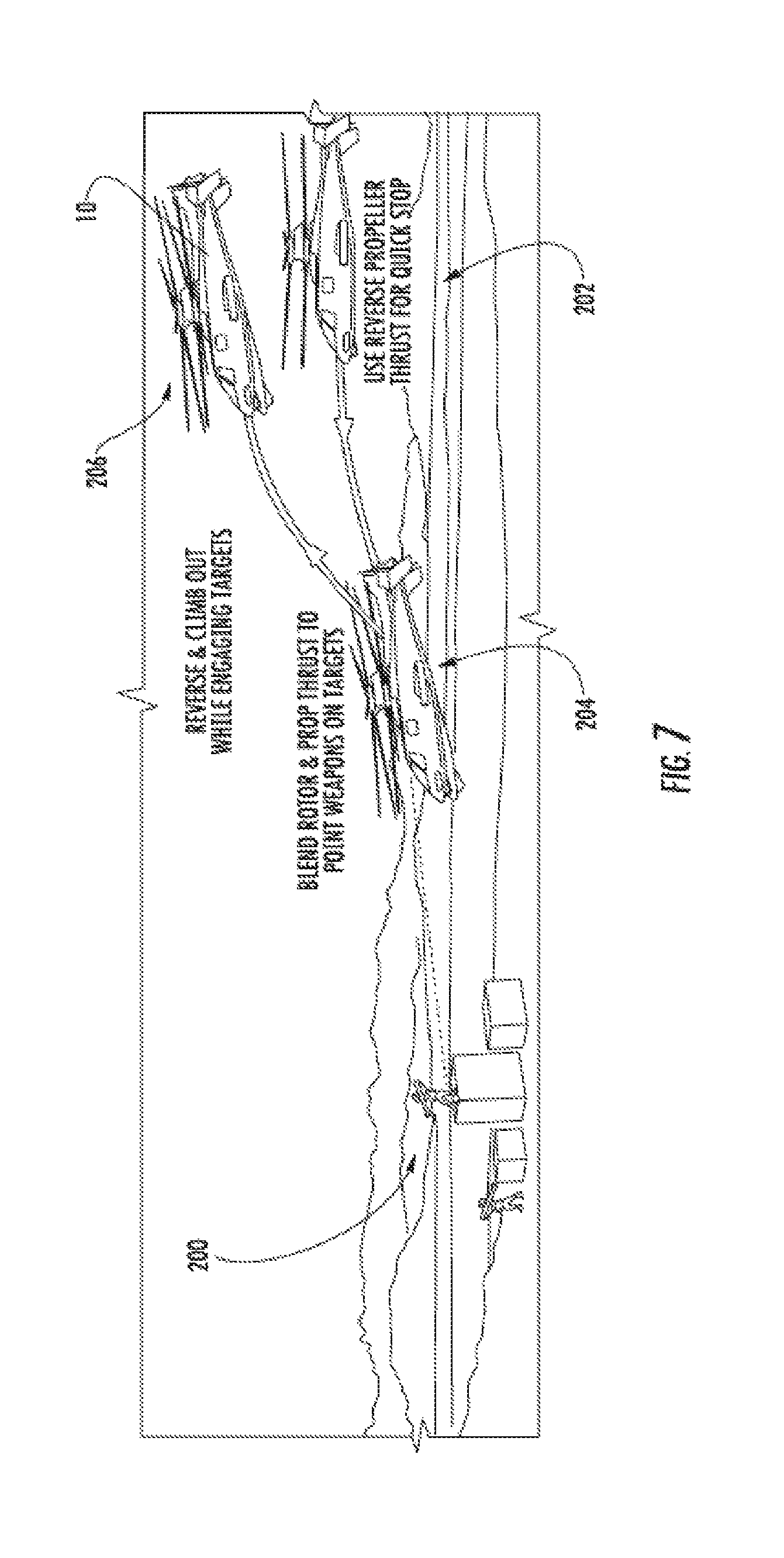
D00014

D00015
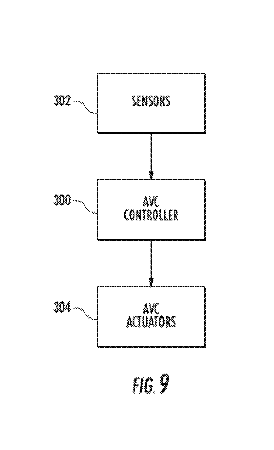
D00016
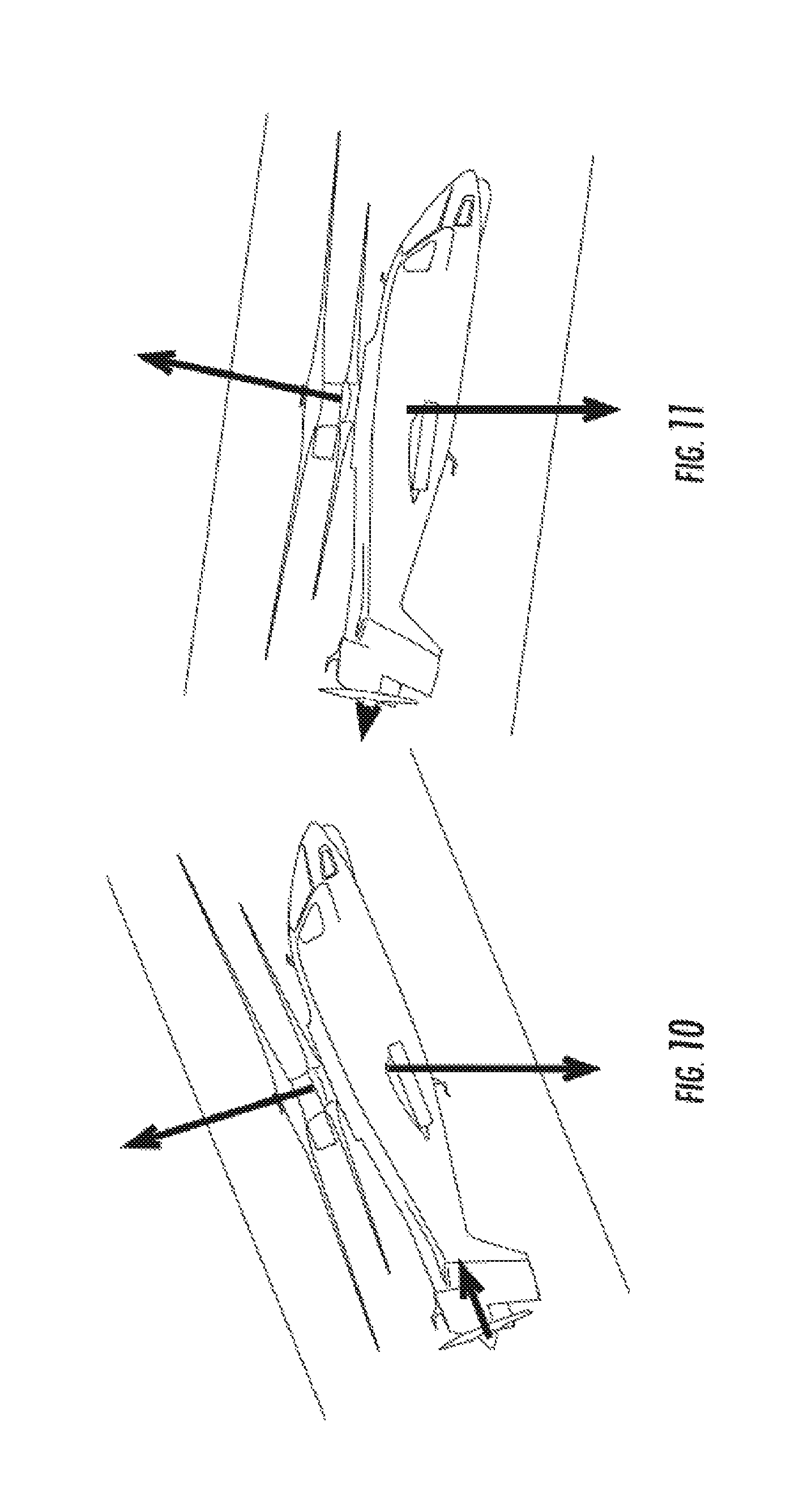
D00017
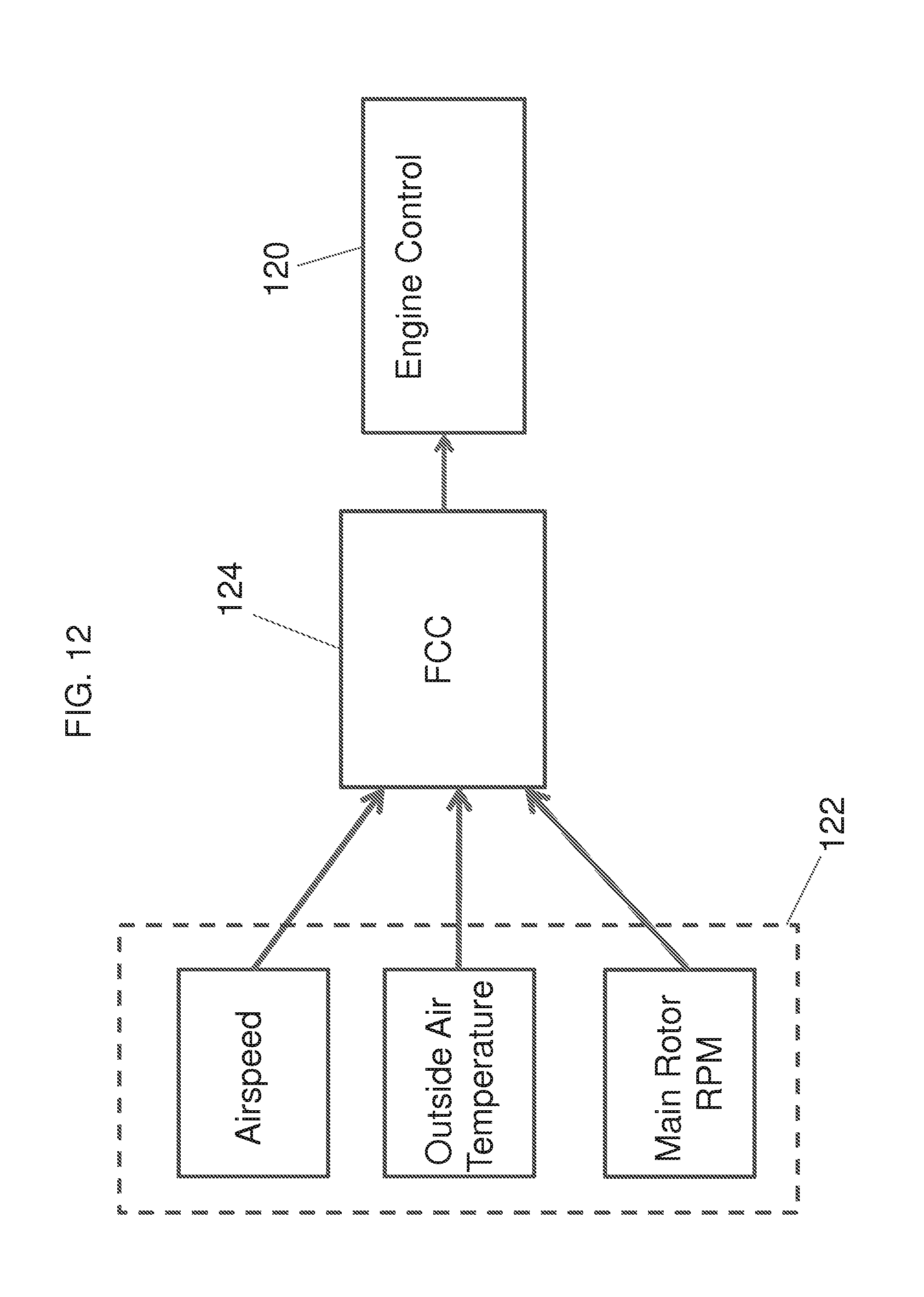
XML
uspto.report is an independent third-party trademark research tool that is not affiliated, endorsed, or sponsored by the United States Patent and Trademark Office (USPTO) or any other governmental organization. The information provided by uspto.report is based on publicly available data at the time of writing and is intended for informational purposes only.
While we strive to provide accurate and up-to-date information, we do not guarantee the accuracy, completeness, reliability, or suitability of the information displayed on this site. The use of this site is at your own risk. Any reliance you place on such information is therefore strictly at your own risk.
All official trademark data, including owner information, should be verified by visiting the official USPTO website at www.uspto.gov. This site is not intended to replace professional legal advice and should not be used as a substitute for consulting with a legal professional who is knowledgeable about trademark law.