System and method for controlling the position of a levitated rotor
Yu , et al. J
U.S. patent number 10,166,318 [Application Number 15/042,431] was granted by the patent office on 2019-01-01 for system and method for controlling the position of a levitated rotor. This patent grant is currently assigned to TC1 LLC. The grantee listed for this patent is TC1 LLC. Invention is credited to Alexander Medvedev, Ren You, Shunzhou Yu.


View All Diagrams
| United States Patent | 10,166,318 |
| Yu , et al. | January 1, 2019 |
System and method for controlling the position of a levitated rotor
Abstract
A rotary machine is provided which may include a rotor and a stator within a housing. The stator may be for generating a rotating magnetic field for applying a torque to the rotor. A commutator circuit may provide a plurality of phase voltages to the stator, and a controller may adjust the plurality of phase voltages provided by the commutator circuit to modify an attractive force of the stator on the rotor to move the rotor in an axial direction.
| Inventors: | Yu; Shunzhou (Ann Arbor, MI), Medvedev; Alexander (Ann Arbor, MI), You; Ren (Windsor, CA) | ||||||||||
|---|---|---|---|---|---|---|---|---|---|---|---|
| Applicant: |
|
||||||||||
| Assignee: | TC1 LLC (Pleasanton,
CA) |
||||||||||
| Family ID: | 56614941 | ||||||||||
| Appl. No.: | 15/042,431 | ||||||||||
| Filed: | February 12, 2016 |
Prior Publication Data
| Document Identifier | Publication Date | |
|---|---|---|
| US 20160235899 A1 | Aug 18, 2016 | |
Related U.S. Patent Documents
| Application Number | Filing Date | Patent Number | Issue Date | ||
|---|---|---|---|---|---|
| 62115603 | Feb 12, 2015 | ||||
| 62115324 | Feb 12, 2015 | ||||
| Current U.S. Class: | 1/1 |
| Current CPC Class: | A61M 1/1015 (20140204); A61M 1/1086 (20130101); A61M 1/1031 (20140204); A61M 2205/3334 (20130101); A61M 1/101 (20130101); A61M 1/1012 (20140204); A61M 1/122 (20140204); A61M 1/1017 (20140204); A61M 2205/3306 (20130101); A61M 1/1013 (20140204); A61M 2205/3317 (20130101) |
| Current International Class: | A61M 1/10 (20060101); A61M 1/12 (20060101) |
References Cited [Referenced By]
U.S. Patent Documents
| 1093868 | April 1914 | Leighty |
| 2684035 | July 1954 | Kemp |
| 3023334 | February 1962 | Burr et al. |
| 3510229 | May 1970 | Smith |
| 3620638 | November 1971 | Kaye et al. |
| 3870382 | March 1975 | Reinhoudt |
| 3932069 | January 1976 | Giardini et al. |
| 3960468 | June 1976 | Boorse et al. |
| 4149535 | April 1979 | Voider |
| 4382199 | May 1983 | Isaacson |
| 4392836 | June 1983 | Sugawara |
| 4434389 | February 1984 | Langley et al. |
| 4507048 | March 1985 | Belenger et al. |
| 4528485 | July 1985 | Boyd, Jr. |
| 4540402 | September 1985 | Aigner |
| 4549860 | October 1985 | Yakich |
| 4645961 | February 1987 | Maisky |
| 4686982 | August 1987 | Nash |
| 4688998 | August 1987 | Olsen et al. |
| 4753221 | June 1988 | Kensey et al. |
| 4763032 | August 1988 | Bramm |
| 4769006 | September 1988 | Papatonakos |
| 4779614 | October 1988 | Moise |
| 4790843 | December 1988 | Carpentier et al. |
| 4806080 | February 1989 | Mizobuchi et al. |
| 4817586 | April 1989 | Wampler |
| 4846152 | July 1989 | Wampler et al. |
| 4857781 | August 1989 | Shih |
| 4888011 | December 1989 | Kung et al. |
| 4895557 | January 1990 | Moise et al. |
| 4900227 | February 1990 | Troup Iin |
| 4902272 | February 1990 | Milder et al. |
| 4906229 | March 1990 | Wampler |
| 4908012 | March 1990 | Moise et al. |
| 4919647 | April 1990 | Nash |
| 4930997 | June 1990 | Bennett |
| 4944722 | July 1990 | Carriker et al. |
| 4957504 | September 1990 | Chardack |
| 4964864 | October 1990 | Summers et al. |
| 4969865 | November 1990 | Hwang et al. |
| 4985014 | January 1991 | Orejola |
| 4995857 | February 1991 | Arnold |
| 5021048 | June 1991 | Buckholtz |
| 5078741 | January 1992 | Bramm et al. |
| 5092844 | March 1992 | Schwartz et al. |
| 5092879 | March 1992 | Jarvik |
| 5100374 | March 1992 | Kageyama |
| 5106263 | April 1992 | Irie |
| 5106273 | April 1992 | Lemarquand et al. |
| 5106372 | April 1992 | Ranford |
| 5112202 | May 1992 | Ozaki et al. |
| 5129883 | July 1992 | Black |
| 5145333 | September 1992 | Smith |
| 5147186 | September 1992 | Buckholtz |
| 5112349 | December 1992 | Summers et al. |
| 5190528 | February 1993 | Fonger et al. |
| 5201679 | April 1993 | Velte et al. |
| 5211546 | May 1993 | Isaacson et al. |
| 5229693 | July 1993 | Futami et al. |
| 5275580 | January 1994 | Yamazaki |
| 5290227 | January 1994 | Pasque |
| 5360445 | January 1994 | Goldowsky |
| 5290236 | March 1994 | Mathewson |
| 5300112 | April 1994 | Barr |
| 5306295 | April 1994 | Kolff et al. |
| 5312341 | May 1994 | Turi |
| 5313128 | May 1994 | Robinson et al. |
| 5332374 | July 1994 | Kricker et al. |
| 5346458 | September 1994 | Afield |
| 5350283 | September 1994 | Nakazeki et al. |
| 5354331 | November 1994 | Schachar |
| 5370509 | December 1994 | Golding et al. |
| 5376114 | December 1994 | Jarvik |
| 5385581 | January 1995 | Bramm et al. |
| 5405383 | November 1995 | Barr |
| 5449342 | December 1995 | Hirose et al. |
| 5478222 | December 1995 | Heidelberg et al. |
| 5504978 | April 1996 | Meyer, III |
| 5507629 | April 1996 | Jarvik |
| 5519270 | May 1996 | Yamada et al. |
| 5533957 | September 1996 | Aldea |
| 5569111 | October 1996 | Cho et al. |
| 5575630 | November 1996 | Nakazawa et al. |
| 5588812 | December 1996 | Taylor et al. |
| 5595762 | January 1997 | Derrieu et al. |
| 5643226 | January 1997 | Cosgrove et al. |
| 5611679 | March 1997 | Ghosh et al. |
| 5613935 | March 1997 | Jarvik |
| 5630836 | May 1997 | Prem et al. |
| 5678306 | October 1997 | Bozeman, Jr. et al. |
| 5692882 | December 1997 | Bozeman, Jr. et al. |
| 5695471 | December 1997 | Wampler |
| 5708346 | January 1998 | Schob |
| 5725357 | March 1998 | Nakazeki et al. |
| 5738649 | April 1998 | Macoviak |
| 5746575 | May 1998 | Westphal et al. |
| 5746709 | May 1998 | Rom et al. |
| 5755784 | May 1998 | Jarvik |
| 5776111 | July 1998 | Tesio |
| 5795074 | August 1998 | Rahman et al. |
| 5800559 | September 1998 | Higham et al. |
| 5807311 | September 1998 | Palestrant |
| 5814011 | September 1998 | Corace |
| 5824069 | October 1998 | Lemole |
| 5749855 | December 1998 | Reitan |
| 5843129 | December 1998 | Larson et al. |
| 5851174 | December 1998 | Jarvik et al. |
| 5853394 | December 1998 | Tolkoff et al. |
| 5890883 | April 1999 | Golding et al. |
| 5911685 | June 1999 | Siess et al. |
| 5917295 | June 1999 | Mongeau |
| 5917297 | June 1999 | Gerster et al. |
| 5921913 | July 1999 | Siess |
| 5924848 | July 1999 | Izraelev |
| 5924975 | July 1999 | Goldowsky |
| 5928131 | July 1999 | Prem |
| 5938412 | August 1999 | Israelev |
| 5941813 | August 1999 | Sievers et al. |
| 5945753 | August 1999 | Maegawa et al. |
| 5868702 | September 1999 | Stevens et al. |
| 5868703 | September 1999 | Bertolero et al. |
| 5947703 | September 1999 | Nojiri et al. |
| 5951263 | September 1999 | Taylor et al. |
| 5984892 | November 1999 | Bedingham |
| 5964694 | December 1999 | Siess et al. |
| 6004269 | December 1999 | Crowley et al. |
| 6007479 | December 1999 | Rottenberg et al. |
| 6030188 | February 2000 | Nojiri et al. |
| 6042347 | March 2000 | Scholl et al. |
| 6053705 | April 2000 | Schob et al. |
| 6066086 | May 2000 | Antaki et al. |
| 6071093 | June 2000 | Hart |
| 6074180 | June 2000 | Khanwilkar et al. |
| 6080133 | June 2000 | Wampler |
| 6082900 | July 2000 | Takeuchi et al. |
| 6083260 | July 2000 | Aboul-Hosn et al. |
| 6100618 | August 2000 | Schoeb et al. |
| 6058593 | September 2000 | Siess |
| 6123659 | September 2000 | leBlanc et al. |
| 6123726 | September 2000 | Mori et al. |
| 6139487 | October 2000 | Siess |
| 6086527 | November 2000 | Talpade |
| 6142752 | November 2000 | Akamatsu et al. |
| 6143025 | November 2000 | Stobie et al. |
| 6146325 | November 2000 | Lewis et al. |
| 6149683 | November 2000 | Lancisi et al. |
| 6158984 | December 2000 | Cao et al. |
| 6171078 | January 2001 | Schob |
| 6176822 | January 2001 | Nix et al. |
| 6176848 | January 2001 | Rau et al. |
| 6179773 | January 2001 | Prem et al. |
| 6190304 | February 2001 | Downey et al. |
| 6200260 | March 2001 | Bolling |
| 6206659 | March 2001 | Izraelev |
| 6254359 | March 2001 | Aber |
| 6222290 | April 2001 | Schob et al. |
| 6227797 | May 2001 | Watterson et al. |
| 6227820 | May 2001 | Jarvik |
| 6234772 | May 2001 | Wampler et al. |
| 6234998 | May 2001 | Wampler |
| 6247892 | June 2001 | Kazatchkov et al. |
| 6249067 | June 2001 | Schob et al. |
| 6264635 | July 2001 | Wampler |
| 6268675 | July 2001 | Amrhein |
| 6276831 | August 2001 | Takahashi et al. |
| 6293901 | September 2001 | Prem |
| 6295877 | October 2001 | Aboul-Hosn et al. |
| 6319231 | November 2001 | Andrulitis |
| 6320731 | November 2001 | Eeaves et al. |
| 6245007 | December 2001 | Bedingham et al. |
| 6458163 | January 2002 | Slemker et al. |
| 6351048 | February 2002 | Schob et al. |
| 6355998 | March 2002 | Schob et al. |
| 6365996 | April 2002 | Schob |
| 6375607 | April 2002 | Prem |
| 6387037 | May 2002 | Bolling et al. |
| 6394769 | May 2002 | Bearnson et al. |
| 6422990 | July 2002 | Prem |
| 6425007 | July 2002 | Messinger |
| 6428464 | August 2002 | Bolling |
| 6439845 | August 2002 | Veres |
| 6447266 | September 2002 | Antaki et al. |
| 6447441 | September 2002 | Yu et al. |
| 6508777 | January 2003 | Macoviak et al. |
| 6508787 | January 2003 | Erbel et al. |
| 6517315 | February 2003 | Belady |
| 6522093 | February 2003 | Hsu et al. |
| 6532964 | March 2003 | Aboul-Hosn et al. |
| 6533716 | March 2003 | Schmitz-Rode et al. |
| 6544216 | April 2003 | Sammler et al. |
| 6547519 | April 2003 | deBlanc et al. |
| 6547530 | April 2003 | Ozaki et al. |
| 6575717 | June 2003 | Ozaki et al. |
| 6589030 | July 2003 | Ozaki |
| 6595762 | July 2003 | Khanwilkar et al. |
| 6605032 | August 2003 | Benkowski et al. |
| 6609883 | August 2003 | Woodard et al. |
| 6610004 | August 2003 | Viole et al. |
| 6623420 | September 2003 | Reich et al. |
| 6641378 | November 2003 | Davis et al. |
| 6641558 | November 2003 | Aboul-Hosn et al. |
| 6688861 | February 2004 | Wampler |
| 6692318 | February 2004 | McBride |
| 6698097 | March 2004 | Miura et al. |
| 6709418 | March 2004 | Aboul-Hosn et al. |
| 6716157 | April 2004 | Goldowsky |
| 6716189 | April 2004 | Jarvik et al. |
| 6732501 | May 2004 | Yu et al. |
| 6749598 | June 2004 | Keren et al. |
| 6776578 | August 2004 | Belady |
| 6790171 | September 2004 | Griindeman et al. |
| 6794789 | September 2004 | Siess et al. |
| 6808371 | October 2004 | Niwatsukino et al. |
| 6817836 | November 2004 | Nose et al. |
| 6846168 | January 2005 | Davis et al. |
| 6860713 | January 2005 | Hoover |
| 6884210 | April 2005 | Nose et al. |
| 6935344 | August 2005 | Aboul-Hosn et al. |
| 6926662 | September 2005 | Aboul-Hosn et al. |
| 6942672 | September 2005 | Heilman et al. |
| 6949066 | September 2005 | Beamson et al. |
| 6966748 | November 2005 | Woodard et al. |
| 6974436 | December 2005 | Aboul-Hosn et al. |
| 6991595 | January 2006 | Burke et al. |
| 7010954 | March 2006 | Siess et al. |
| 7011620 | March 2006 | Siess |
| 7022100 | April 2006 | Aboul-Hosn et al. |
| 7048681 | May 2006 | Tsubouchi et al. |
| 7089059 | August 2006 | Pless |
| 7090401 | August 2006 | Rahman et al. |
| 7112903 | September 2006 | Schob |
| 7122019 | October 2006 | Kesten et al. |
| 7128538 | October 2006 | Tsubouchi et al. |
| 7027875 | November 2006 | Siess et al. |
| 7156802 | January 2007 | Woodard et al. |
| 7160243 | January 2007 | Medvedev |
| 7175588 | February 2007 | Morello |
| 7202582 | April 2007 | Eckert et al. |
| 7172551 | June 2007 | Leasure |
| 7241257 | October 2007 | Ainsworth et al. |
| 7284956 | October 2007 | Nose et al. |
| 7331921 | February 2008 | Viole et al. |
| 7335192 | February 2008 | Keren et al. |
| 7393181 | July 2008 | McBride et al. |
| 7431688 | October 2008 | Wampler et al. |
| 7329236 | December 2008 | Kesten et al. |
| 7462019 | December 2008 | Allarie et al. |
| 7467930 | December 2008 | Ozaki et al. |
| 7470246 | December 2008 | Mori et al. |
| 7476077 | January 2009 | Woodard et al. |
| 7491163 | February 2009 | Viole et al. |
| 7575423 | August 2009 | Wampler |
| 7645225 | January 2010 | Medvedev et al. |
| 7660635 | February 2010 | Verness et al. |
| 7699586 | April 2010 | LaRose et al. |
| 7748964 | July 2010 | Yaegashi et al. |
| 7731675 | August 2010 | Aboul-Hosn et al. |
| 7802966 | September 2010 | Wampler et al. |
| 7841976 | November 2010 | McBride et al. |
| 7862501 | January 2011 | Woodard |
| 7888242 | February 2011 | Tanaka et al. |
| 7934909 | May 2011 | Nuesser et al. |
| 7972122 | July 2011 | LaRose et al. |
| 7976271 | July 2011 | LaRose et al. |
| 7997854 | August 2011 | LaRose et al. |
| 8007254 | August 2011 | LaRose et al. |
| 8096935 | January 2012 | Sutton et al. |
| 8123669 | February 2012 | Siess et al. |
| 8152493 | April 2012 | LaRose et al. |
| 8177703 | May 2012 | Smith et al. |
| 8226373 | July 2012 | Yaehashi |
| 8282359 | October 2012 | Ayre et al. |
| 8283829 | October 2012 | Yamamoto et al. |
| 8366381 | February 2013 | Woodard et al. |
| 8403823 | March 2013 | Yu et al. |
| 8512012 | August 2013 | Mustafa et al. |
| 8535211 | September 2013 | Campbell et al. |
| 8585290 | November 2013 | Bauer |
| 8686674 | April 2014 | Bi et al. |
| 8770945 | July 2014 | Ozaki et al. |
| 8821365 | September 2014 | Ozaki et al. |
| 8827661 | September 2014 | Mori |
| 8652024 | October 2014 | Yanai et al. |
| 8864644 | October 2014 | Yomtov |
| 8870552 | October 2014 | Ayre et al. |
| 8968174 | March 2015 | Yanai et al. |
| 9039595 | May 2015 | Ayre et al. |
| 9067005 | June 2015 | Ozaki et al. |
| 9068572 | June 2015 | Ozaki et al. |
| 9109601 | August 2015 | Mori |
| 9132215 | September 2015 | Ozaki et al. |
| 9133854 | September 2015 | Okawa et al. |
| 9371826 | June 2016 | Yanai et al. |
| 9381285 | July 2016 | Ozaki et al. |
| 9382908 | July 2016 | Ozaki et al. |
| 9410549 | August 2016 | Ozaki et al. |
| 9556873 | January 2017 | Yanai et al. |
| 2001/0039369 | November 2001 | Terentiev |
| 2002/0051711 | May 2002 | Ozaki |
| 2002/0058994 | May 2002 | Hill et al. |
| 2002/0094281 | July 2002 | Khanwilkar et al. |
| 2002/0095210 | July 2002 | Finnegan et al. |
| 2003/0023302 | January 2003 | Moe et al. |
| 2003/0045772 | March 2003 | Reich et al. |
| 2003/0072656 | April 2003 | Niwatsukino et al. |
| 2003/0144574 | July 2003 | Heilman et al. |
| 2003/0199727 | October 2003 | Burke |
| 2003/0236488 | December 2003 | Novak |
| 2003/0236490 | December 2003 | Novak |
| 2004/0007515 | January 2004 | Geyer |
| 2004/0015232 | January 2004 | Shu et al. |
| 2004/0024285 | February 2004 | Muckter |
| 2004/0030381 | February 2004 | Shu |
| 2004/0064012 | April 2004 | Yanai |
| 2004/0143151 | July 2004 | Mori et al. |
| 2004/0145337 | July 2004 | Morishita |
| 2004/0152944 | August 2004 | Medvedev et al. |
| 2004/0171905 | September 2004 | Yu et al. |
| 2004/0210305 | October 2004 | Shu et al. |
| 2004/0215050 | October 2004 | Morello |
| 2004/0263341 | December 2004 | Enzinna |
| 2005/0004418 | January 2005 | Morello |
| 2005/0008496 | January 2005 | Tsubouchi et al. |
| 2005/0025630 | February 2005 | Ayre et al. |
| 2005/0043665 | February 2005 | Vinci et al. |
| 2005/0073273 | April 2005 | Maslov et al. |
| 2005/0089422 | April 2005 | Ozaki et al. |
| 2005/0131271 | June 2005 | Benkowski et al. |
| 2005/0141887 | June 2005 | Lelkes |
| 2005/0194851 | September 2005 | Eckert et al. |
| 2005/0261542 | November 2005 | Abe et al. |
| 2005/0287022 | December 2005 | Yaegashi et al. |
| 2006/0024182 | February 2006 | Akdis et al. |
| 2006/0055274 | March 2006 | Kim |
| 2006/0127227 | June 2006 | Mehlhorn et al. |
| 2007/0073393 | March 2007 | Kung et al. |
| 2007/0078293 | April 2007 | Shambaugh, Jr. |
| 2007/0095648 | April 2007 | Wampler et al. |
| 2007/0114961 | May 2007 | Schwarzkopf |
| 2007/0134993 | June 2007 | Tamez et al. |
| 2007/0189648 | August 2007 | Kita et al. |
| 2007/0213690 | September 2007 | Phillips et al. |
| 2007/0231135 | October 2007 | Wampler et al. |
| 2007/0282298 | December 2007 | Mason |
| 2007/0297923 | December 2007 | Tada |
| 2008/0007196 | January 2008 | Tan et al. |
| 2008/0021394 | January 2008 | La Rose et al. |
| 2008/0030895 | February 2008 | Obara et al. |
| 2008/0119777 | May 2008 | Vinci et al. |
| 2008/0124231 | May 2008 | Yaegashi |
| 2008/0183287 | July 2008 | Ayre |
| 2008/0211439 | September 2008 | Yokota et al. |
| 2008/0281146 | November 2008 | Morello |
| 2009/0041595 | February 2009 | Garzaniti et al. |
| 2009/0060743 | March 2009 | McBride et al. |
| 2009/0074336 | March 2009 | Engesser et al. |
| 2009/0099406 | April 2009 | Salmonsen et al. |
| 2009/0171136 | July 2009 | Shambaugh, Jr. |
| 2009/0257693 | October 2009 | Aiello |
| 2009/0318834 | December 2009 | Fujiwara et al. |
| 2010/0185280 | June 2010 | Ayre et al. |
| 2010/0168534 | July 2010 | Matsumoto et al. |
| 2010/0222634 | September 2010 | Poirier |
| 2010/0234835 | September 2010 | Horikawa et al. |
| 2010/0256440 | October 2010 | Maher |
| 2010/0262039 | October 2010 | Fujiwara et al. |
| 2010/0266423 | October 2010 | Gohean et al. |
| 2010/0305692 | December 2010 | Thomas et al. |
| 2010/0324465 | December 2010 | Vinci et al. |
| 2011/0015732 | January 2011 | Kanebako |
| 2011/0112354 | May 2011 | Nishimura et al. |
| 2011/0118766 | May 2011 | Reichenbach et al. |
| 2011/0118829 | May 2011 | Hoarau et al. |
| 2011/0118833 | May 2011 | Reichenbach et al. |
| 2011/0129373 | June 2011 | Mori |
| 2011/0160519 | June 2011 | Arndt et al. |
| 2011/0218383 | September 2011 | Broen et al. |
| 2011/0218384 | September 2011 | Bachman et al. |
| 2011/0218385 | September 2011 | Bolyard et al. |
| 2011/0237978 | September 2011 | Fujiwara et al. |
| 2011/0243759 | October 2011 | Ozaki et al. |
| 2011/0318203 | December 2011 | Ozaki et al. |
| 2012/0003108 | January 2012 | Ozaki et al. |
| 2012/0016178 | January 2012 | Woodard et al. |
| 2012/0022645 | January 2012 | Burke |
| 2012/0035411 | February 2012 | LaRose et al. |
| 2012/0078030 | March 2012 | Bourque |
| 2012/0078031 | March 2012 | Burke et al. |
| 2012/0095281 | April 2012 | Reichenbach et al. |
| 2012/0130152 | May 2012 | Ozaki et al. |
| 2012/0226350 | September 2012 | Ruder et al. |
| 2012/0243759 | September 2012 | Fujisawa |
| 2012/0245680 | September 2012 | Masuzawa |
| 2012/0245681 | September 2012 | Casas et al. |
| 2012/0253103 | October 2012 | Jarvik |
| 2012/0308363 | December 2012 | Ozaki et al. |
| 2013/0030240 | January 2013 | Schima et al. |
| 2013/0121821 | May 2013 | Ozaki et al. |
| 2013/0158521 | June 2013 | Sobue |
| 2013/0170970 | July 2013 | Ozaki et al. |
| 2013/0178694 | July 2013 | Jeffery et al. |
| 2013/0225909 | August 2013 | Dormanen et al. |
| 2013/0243623 | September 2013 | Okawa et al. |
| 2013/0289334 | October 2013 | Badstibner et al. |
| 2013/0331711 | December 2013 | Mathur et al. |
| 2014/0030122 | January 2014 | Ozaki et al. |
| 2014/0066690 | March 2014 | Siebenhaar et al. |
| 2014/0066691 | March 2014 | Siebenhaar |
| 2014/0100413 | April 2014 | Casas et al. |
| 2014/0107399 | April 2014 | Spence |
| 2014/0142367 | May 2014 | Ayre et al. |
| 2014/0155682 | June 2014 | Jeffery et al. |
| 2014/0200389 | July 2014 | Yanai et al. |
| 2014/0205467 | July 2014 | Yanai et al. |
| 2014/0241904 | August 2014 | Yanai et al. |
| 2014/0275721 | September 2014 | Yanai et al. |
| 2014/0275727 | September 2014 | Bonde et al. |
| 2014/0296615 | October 2014 | Franano |
| 2014/0309481 | October 2014 | Medvedev et al. |
| 2014/0314597 | October 2014 | Allaire et al. |
| 2014/0323796 | October 2014 | Medvedev et al. |
| 2014/0343352 | November 2014 | Ardt et al. |
| 2015/0017030 | January 2015 | Ozaki |
| 2015/0023803 | January 2015 | Fritz et al. |
| 2015/0078936 | March 2015 | Mori |
| 2015/0306290 | October 2015 | Rosenberg et al. |
| 2015/0367048 | December 2015 | Brown et al. |
| 2015/0374892 | December 2015 | Yanai et al. |
| 2016/0058929 | March 2016 | Medvedev et al. |
| 2016/0058930 | March 2016 | Medvedev et al. |
| 2016/0228628 | August 2016 | Medvedev et al. |
| 2016/0235898 | August 2016 | Yanai et al. |
| 2016/0235900 | August 2016 | Yanai et al. |
| 2016/0281720 | September 2016 | Yanai et al. |
| 2016/0281728 | September 2016 | Ozaki et al. |
| 1347585 | May 2002 | CN | |||
| 1462344 | Dec 2003 | CN | |||
| 102239334 | Nov 2011 | CN | |||
| 102341600 | Feb 2012 | CN | |||
| 2945662 | Sep 1999 | EP | |||
| 971212 | Jan 2000 | EP | |||
| 1113117 | Jul 2001 | EP | |||
| 1327455 | Jul 2003 | EP | |||
| 1430919 | Jun 2004 | EP | |||
| 1495773 | Jan 2005 | EP | |||
| 1598087 | Mar 2005 | EP | |||
| 1526286 | Apr 2005 | EP | |||
| 1495773 | Nov 2006 | EP | |||
| 1495773 | Feb 2009 | EP | |||
| 2292282 | Mar 2011 | EP | |||
| 2298375 | Mar 2011 | EP | |||
| 2372160 | Oct 2011 | EP | |||
| 2405140 | Jan 2012 | EP | |||
| 2405141 | Jan 2012 | EP | |||
| 2461465 | Jun 2012 | EP | |||
| 2538086 | Dec 2012 | EP | |||
| 2554191 | Feb 2013 | EP | |||
| 2594799 | May 2013 | EP | |||
| 2618001 | Jul 2013 | EP | |||
| 2693609 | Feb 2014 | EP | |||
| 2948202 | Dec 2015 | EP | |||
| 2961987 | Jan 2016 | EP | |||
| 3013385 | May 2016 | EP | |||
| 58/9535 | Jan 1983 | JP | |||
| 61/293146 | Dec 1986 | JP | |||
| 04/091396 | Mar 1992 | JP | |||
| 04/148094 | May 1992 | JP | |||
| 05/021197 | Mar 1993 | JP | |||
| 06/014538 | Feb 1994 | JP | |||
| 06/053790 | Jul 1994 | JP | |||
| 2006/070476 | Sep 1994 | JP | |||
| 2006/245455 | Sep 1994 | JP | |||
| 07/014220 | Mar 1995 | JP | |||
| 07/042869 | Aug 1995 | JP | |||
| 07/509156 | Oct 1995 | JP | |||
| 09/122228 | May 1997 | JP | |||
| 10/331841 | Dec 1998 | JP | |||
| 11/244377 | Sep 1999 | JP | |||
| 2001/309628 | Nov 2001 | JP | |||
| 2003/135592 | May 2003 | JP | |||
| 2004/166401 | Jun 2004 | JP | |||
| 2004/209240 | Jul 2004 | JP | |||
| 2004/332566 | Nov 2004 | JP | |||
| 2004/346925 | Dec 2004 | JP | |||
| 2005/094955 | Apr 2005 | JP | |||
| 2005/127222 | May 2005 | JP | |||
| 2005/245138 | Sep 2005 | JP | |||
| 2005/270345 | Oct 2005 | JP | |||
| 2005/270415 | Oct 2005 | JP | |||
| 2005/287599 | Oct 2005 | JP | |||
| 2006/167173 | Jun 2006 | JP | |||
| 2007/002885 | Jan 2007 | JP | |||
| 2007/043821 | Feb 2007 | JP | |||
| 2007/089972 | Apr 2007 | JP | |||
| 2007/089974 | Apr 2007 | JP | |||
| 2007/215292 | Aug 2007 | JP | |||
| 2007/247489 | Sep 2007 | JP | |||
| 2008/011611 | Jan 2008 | JP | |||
| 2008/104278 | May 2008 | JP | |||
| 2008/132131 | Jun 2008 | JP | |||
| 2008/99453 | Aug 2008 | JP | |||
| 2008/193838 | Aug 2008 | JP | |||
| 2008/297997 | Dec 2008 | JP | |||
| 2008/301634 | Dec 2008 | JP | |||
| 2006/254619 | Sep 2009 | JP | |||
| 2010/133381 | Jun 2010 | JP | |||
| 2010/136863 | Jun 2010 | JP | |||
| 2010/203398 | Sep 2010 | JP | |||
| 2010/209691 | Sep 2010 | JP | |||
| 2011/169166 | Sep 2011 | JP | |||
| 2012/021413 | Feb 2012 | JP | |||
| 2012/062790 | Mar 2012 | JP | |||
| 5171953 | Mar 2013 | JP | |||
| 5572832 | Aug 2014 | JP | |||
| 5656835 | Jan 2015 | JP | |||
| 1993/07388 | Apr 1993 | WO | |||
| 94/14226 | Jun 1994 | WO | |||
| 1996/31934 | Oct 1996 | WO | |||
| 1997/42413 | Nov 1997 | WO | |||
| 2000/64509 | Nov 2000 | WO | |||
| 2004/098677 | Nov 2004 | WO | |||
| 2005/011087 | Feb 2005 | WO | |||
| 2005/028000 | Mar 2005 | WO | |||
| 2005/034312 | Apr 2005 | WO | |||
| 2009/157408 | Dec 2009 | WO | |||
| 2010/067682 | Jun 2010 | WO | |||
| 2010/101082 | Sep 2010 | WO | |||
| 2010/101107 | Sep 2010 | WO | |||
| 2011/013483 | Feb 2011 | WO | |||
| 2012/036059 | Mar 2012 | WO | |||
| 2012/040544 | Mar 2012 | WO | |||
| 2012/047550 | Apr 2012 | WO | |||
| 2012/132850 | Oct 2012 | WO | |||
| 2014/113533 | Jul 2014 | WO | |||
| 2014/116676 | Jul 2014 | WO | |||
| 2014/133942 | Sep 2014 | WO | |||
| 2014/179271 | Nov 2014 | WO | |||
| 2016/033131 | Mar 2016 | WO | |||
| 2016/033133 | Mar 2016 | WO | |||
| 2016/130846 | Aug 2016 | WO | |||
| 2016/130944 | Aug 2016 | WO | |||
| 2016/130955 | Aug 2016 | WO | |||
| 2016/130989 | Aug 2016 | WO | |||
Other References
|
European office action dated Oct. 31, 2016 for EP 10804230.0, all pages. cited by applicant . European Office Action issued in Application No. EP 11825062 dated Jul. 19, 2016, all pages. cited by applicant . Gieras, et al., "Advancements in Electric Machines", Nov. 14, 2008, pp. 43-48. cited by applicant . International Search Report and Written Opinion of PCT/US2016/062284, dated Feb. 24, 2017, all pages. cited by applicant . European office action dated Jul. 22, 2016 for European Patent Application No. EP 09770118.9, all pages. cited by applicant . European office action dated Sep. 8, 2016 for EP 14741174, all pages. cited by applicant . Extended European Search Report for EP 14 74 3371 dated Sep. 29, 2016, all pages. cited by applicant . International Search Report and Written Opinion of PCT/US2015/046844, dated Oct. 27, 2015, all pages. cited by applicant . International Search Report and Written Opinion of PCT/US2015/046846, dated Oct. 27, 2015, all pages. cited by applicant . European office action dated Jan. 27, 2016 for EP 10804230.0, all pages. cited by applicant . Extended European Search Report dated Feb. 4, 2016 in European Patent Application No. EP 12764433.4, filed Mar. 12, 2012, all pages. cited by applicant . International Preliminary Report on Patentability dated Jul. 30, 2015 for International Patent Application No. PCT/US2014/011786, filed on Jan. 16, 2014, all pages. cited by applicant . International Search Report and Written Opinion of PCT/US2014/012511, dated May 147, 2014, all pages. cited by applicant . International Search Report and Written Opinion of PCT/US2014/017932, dated Jun. 16, 2014, all pages. cited by applicant . International Preliminary Report on Patentability dated Sep. 11, 2015 for International Patent Application No. PCT/US2014/017932, filed on Feb. 24, 2014, all pages. cited by applicant . International Search Report and Written Opinion of PCT/US2014/035798, dated Feb. 11, 2016, all pages. cited by applicant . International Search Report and Written Opinion of PCT/US2016/017611, dated May 16, 2016, all pages. cited by applicant . International Search Report and Written Opinion of PCT/US2016/017791, dated May 16, 2016, all pages. cited by applicant . Japanese office action dated Dec. 11, 2015 JP 2013-507344, all pages. cited by applicant . Asama, J., et al., "A Compact Highly Efficient and Low Hemolytic Centrifugal Blood Pump With a Magnetically Levitated Impeller", Artificial Organs, vol. 30, No. 3, Mar. 1, 2006 (Mar. 1, 2006), pp. 160-167. cited by applicant . Asama, J., et al.,"A New Design for a Compact Centrifugal Blood Pump with a Magnetically Levitated Rotor", Asaio Jopurnal, vol. 50, No. 6, Nov. 1, 2004 (Nov. 1, 2004), pp. 550-556. cited by applicant . Asama, et al., "Suspension Performance of a Two-Axis Actively Regulated Consequent-Pole Bearingless Motor," IEEE Transactions on Energy Conversion, vol. 28, No. 4, Dec. 2013, 8 pages. cited by applicant . European Search report Issued in European Patent Application No. 10748702.7, dated Apr. 2, 2013. cited by applicant . Extended European Search Report issued in European Patent Application No. EP 10748677.1, dated Nov. 19, 2012. cited by applicant . Extended European Search Report issued in European Patent Application No. EP 11825062.0, dated Jun. 18, 2015, all pages. cited by applicant . Extended European Search Report issued in European Patent Application No. EP 11806627.3, dated Oct. 8, 2014, all pages. cited by applicant . Extended European Search Report dated Mar. 26, 2015 in European Patent Application No. EP 09770118.9 filed Jun. 22, 2009, all pages. cited by applicant . International Search Report (PCT/ISA/210) dated Jul. 14, 2009, by Japanese Patent Office as the International Searching Authority for International Application No. PCT/JP2009/061318. cited by applicant . International Search Report and Written Opinion issued in PCT/JP2011/050925, dated Apr. 12, 2011. cited by applicant . International Search Report and Written Opinion issued in PCT/JP2011/054134, dated Apr. 12, 2011. cited by applicant . International Search Report and Written Opinion issued in PCT/JP2011/064768, dated Sep. 13, 2011. cited by applicant . International Search Report and Written Opinion issued in PCT/JP2011/070450, dated Dec. 13, 2011. cited by applicant . International Search Report and Written Opinion of PCT/US2014/012448 dated Feb. 19, 2014, all pages. cited by applicant . International Search Report and Written Opinion of PCT/US2014/011786 dated May 5, 2014, all pages. cited by applicant . International Search Report and Written Opinion of PCT/US2014/012502 dated May 9, 2014,all pages. cited by applicant . International Search Report and Written Opinion of PCT/US2014/012511 dated May 14, 2014, all pages. cited by applicant . International Preliminary Report on Patentability dated Aug. 6, 2015 for International Patent Application No. PCT/US2014/012511 filed on Jan. 22, 2014, all pages. cited by applicant . International Preliminary Report on Patentability dated Aug. 6, 2015 for International Patent Application No. PCT/US2014/012502 filed on Jan. 22, 2014, all pages. cited by applicant . International Preliminary Report on Patentability dated Feb. 25, 2016 for International Patent Application No. PCT/US2014/035798 filed on Apr. 29, 2014, all pages. cited by applicant . Kosaka, et al., "Operating Point Control Systemt for a Continuous Flow Artificial Heart: In Vitro Study," ASAIO Journal 2003, all pages. cited by applicant . Neethu, S., et al., "Novel design, optimization and realization of axial flux motor for implantable blood pump", Power Electronics, Drives and Energy Systems (PEDES) & 2010 Power Indian, 2010 Joint International Conference on, IEEE, Dec. 20, 2010 (Dec. 20, 2010), pp. 1-6. cited by applicant . Sandtner, J., et al., "Electrodynamic Passive Magnetic Bearing with Planar Halbach Arrays", Aug. 6, 2004 (Aug. 6, 2004), retrieved from the internet: <http://www.silphenix.ch/lexington.pdf>, all pages. cited by applicant . Supplementary European Search Report issued in European Application No. 09831788.6, dated Jan. 7, 2013, all pages. cited by applicant . Terumo Heart, Inc., "Handled With Care--Significantly Reduce the Risk of Cell Damage," Terumo brochure, Apr. 2010, 2 pages. cited by applicant . Yamazaki, et al., "Development of a Miniature Intraventricular Axial Flow Blood Pump," ASAIO Journal, 1993, 7 pages. cited by applicant . International Search Report and Written Opinion of PCT/US2016/017812, dated Jun. 7, 2016, all pages. cited by applicant . International Search Report and Written Opinion of PCT/US2016/017864, dated Jun. 8, 2016, all pages. cited by applicant . Decision to Grant for JP 2013-507344 dated Jun. 14, 2016, all pages. cited by applicant. |
Primary Examiner: Evanisko; George
Attorney, Agent or Firm: Kilpatrick Townsend & Stockton, LLP
Parent Case Text
CROSS-REFERENCE TO RELATED APPLICATION
This application claims priority to U.S. Provisional Application No. 62/115,603, filed Feb. 12, 2015, and entitled "SYSTEM AND METHOD FOR CONTROLLING THE POSITION OF A LEVITATED ROTOR," the entire disclosure of which is hereby incorporated by reference, for all purposes, as if fully set forth herein.
This application also claims priority to U.S. Provisional Application No. 62/115,324, filed Feb. 12, 2015, and entitled "SYSTEM AND METHOD FOR CONTROLLING THE POSITION OF A LEVITATED ROTOR," the entire disclosure of which is hereby incorporated by reference, for all purposes, as if fully set forth herein.
Claims
What is claimed:
1. A method of operating a blood pump, wherein the method comprises: applying a rotating magnetic field with a stator to rotate a rotor; applying a first axial force on the rotor; applying at least a second axial force on the rotor with the stator, wherein a combination of the first axial force and at least the second axial force suspends the rotor at a first balanced position; and modifying a plurality of phase voltages provided to the stator to modify the second axial force such that the rotor is moved from the first balanced position to a second balanced position, wherein the second balanced position is different than the first balanced position.
2. The method according to claim 1, wherein the first axial force comprises a passive magnetic attractive force.
3. The method according to claim 1, wherein the at least second axial force comprises an active magnetic force created by electromagnetic coils of the stator.
4. The method according to claim 3, further comprising controlling the electromagnetic coils with a controller using a vector control algorithm.
5. The method according to claim 1, wherein the method further comprises sensing at least an axial position of the rotor.
6. The method according to claim 1, wherein modifying the at least second axial force occurs, at least in part, in response to the axial position of the rotor.
7. The method according to claim 1, wherein applying at least the second axial force on the rotor comprises adjusting a plurality of phase voltages provided to the stator by varying a commutation angle.
8. The method according to claim 1, wherein the rotor comprises an impeller.
9. The method according to claim 1, wherein modifying the plurality of phase voltages comprises continuously modifying the plurality of phase voltages to move the rotor to the second balanced position and to hold the rotor in the second balanced position.
10. The method according to claim 1, wherein modifying the plurality of phase voltages comprises periodically modifying the plurality of phase voltages to move the rotor to the second balanced position and to hold the rotor in the second balance position.
11. The method according to claim 1, wherein modifying the plurality of phase voltages comprises modifying the plurality of phase voltages in a single pulse to move the rotor to the second balanced position.
12. The method according to claim 1, wherein: after the rotor has moved to the first balanced position, modifying the plurality of phase voltages is not required to maintain the stator in the first balanced position; and after the rotor has moved to the second balanced position, modifying the plurality of phase voltages is not required to maintain the stator in the second balanced position.
Description
BACKGROUND OF THE INVENTION
The present invention relates in general to rotary devices, and more specifically, to improved pumping devices and methods for their control.
One exemplary type of rotary machine is a centrifugal pumping device or mechanical circulatory assist device for treating patients with heart failure. Many types of circulatory assist devices are available for either short term or long term support for patients having cardiovascular disease. For example, a heart pump system known as a left ventricular assist device (LVAD) can provide long term patient support with an implantable pump associated with an externally-worn pump control unit and batteries. The LVAD improves circulation throughout the body by assisting the left side of the heart in pumping blood. Examples of LVAD systems are the DuraHeart.RTM. LVAS system made by Terumo Heart, Inc. of Ann Arbor, Mich. and the HeartMate II.TM. and HeartMate III.TM. systems made by Thoratec Corporation of Pleasanton, Calif. These systems typically employ a centrifugal pump with a magnetically levitated impeller to pump blood from the left ventricle to the aorta. The impeller is formed as the rotor of the electric motor and rotated by the rotating magnetic field from a multiphase stator such as a brushless DC motor (BLDC). The impeller is rotated to provide sufficient blood flow through the pump to the patient's systemic circulation.
Early LVAD systems utilized mechanical bearings such as ball-and-cup bearings. More recent LVADs employ non-contact bearings which levitate the impeller using hydrodynamic and/or magnetic forces. In one example, the impeller is levitated by the combination of hydrodynamic and passive magnetic forces.
There is a trend for making centrifugal blood pumps used as the mechanical circulatory support devices more miniaturized to treat a broader patient population, more reliable, and with improved outcomes. To follow this trend, contactless impeller suspension technology has been developed in several pump designs. The principle of this technology is to levitate the pump impeller using one or a combination of forces from electromagnets, hydrodynamics, and permanent magnets. In the meanwhile, the pump should be hemocompatible to minimize the blood cell damage and blood clot formation. To that end, the bearing gap between the levitated impeller and the pump housing becomes an important factor. A small gap may lead to the high probability of the thrombus formation in the bearing or to elevated hemolysis due to excessive shear stress. Likewise, a large gap can compromise the hydrodynamic bearing performance and the pump efficiency.
One pump design utilizing active magnetic bearings achieves the desired bearing gap by levitating the impeller using magnetic fields generated by electromagnetic coils. However, in such a design there is the need for a separate bearing control system that includes the position sensors and electromagnetic coils to control the impeller position. Another pump design levitates the impeller using hydrodynamic thrust bearings combined with passive magnetic bearings. However, such a design usually requires a small bearing gap to provide sufficient hydrodynamic bearing stiffness to maintain impeller levitation and prevent contacts between impeller and the pump housing. Such a small gap may result in an insufficient washout and vulnerability to blood clotting thus compromising hemocompatibility.
Therefore, a solution is needed to enhance the bearing gap to achieve adequate washout without increasing the complexity of the pump mechanical design and reducing the pump efficiency.
There is a need for a pump that includes an integrated control method for controlling the impeller position to enhance the bearing gap without increasing the complexity of the pump mechanical design and reducing the pump efficiency.
There is the need for a blood pump designed to maintain a centered position of the impeller to limit hemolysis and thrombosis without needing active control of the stationary levitating magnetic field.
There is a need for pumps which overcomes the above and other disadvantages of known designs.
BRIEF SUMMARY OF THE INVENTION
In summary, various aspects of the present invention are directed to a rotary machine including a rotor within a housing and having a rotor magnetic structure; a stator on a side of the housing for generating a rotating magnetic field for applying a torque to the rotor magnetic structure; a commutator circuit for providing a plurality of phase voltages to the stator; and a controller for rotating the rotor using the commutator circuit and a vector control algorithm. In one embodiment the controller is configured to adjust the phase voltages to modify an attractive force of the stator on the rotor magnetic structure to translate the rotor.
In various embodiments, the machine further includes a sensing circuit for determining a position of the rotor. The controller may be configured to calculate successive commanded values for the phase voltages in response to determined phase currents from the sensing circuit and a variable commutation angle. The angle for calculating the commanded values may be determined in response to a phase current characteristic and a rotational speed of the rotor.
In various embodiments, the rotor is levitated by a substantially constant passive magnetic field.
In various embodiments, the controller is configured to move the rotor from a first balanced position to a second balanced position.
Various aspects of the invention are directed to a rotary machine including a rotor within a housing and having a rotor magnetic structure; a bearing mechanism for suspending the rotor in the housing in a balanced, non-contact manner; motor coils on a side of the housing for generating a magnetic field to apply a torque on the rotor magnetic structure; at least a first sensing circuit for determining a rotational and axial position of the rotor; a controller for rotating the rotor using the motor coils; and an impeller position control mechanism for adjusting a position of the impeller in the housing.
In various embodiments, the bearing mechanism comprises one of a hydrodynamic bearing, magnetic bearing, or combination of the same. In various embodiments, the modification of the attractive force on the rotor magnetic structure by the controller causes the rotor to move from a first balanced position to a second balanced position. The sensing circuit may include a plurality of position sensors for detecting the axial and rotational position of the rotor. The plurality of position sensors may include Hall-effect sensors. The plurality of position sensors may include optical sensors. In various embodiments, the rotor magnetic structure includes a plurality of magnetic members.
In various embodiments, the rotary machine is a pump. In various embodiments, the rotary machine is a blood pump. In various embodiments, the rotor is formed as an impeller.
Various aspects of the invention are directed to a method of operating the rotary machine described in any of the paragraphs above.
Various aspects of the invention are directed to a method of operating a centrifugal pump including a stator having windings and an impeller rotating in a non-contact manner within a pump housing, the impeller including a magnetic structure, the method includes applying a first levitating force on the impeller during rotation; and using electromagnetic windings, controlling the position of the impeller in the pump housing axially and rotationally.
In various embodiments, the first levitating force comprises a passive magnetic attractive force. The at least second levitating force may include an active magnetic force created by electromagnetic coils. The coils may be driven by vector control.
Various aspects of the invention are directed to a method of operating a centrifugal pump including a stator having windings and an impeller rotating in a non-contact manner within a pump housing, the impeller including a magnetic structure, the method including applying a first levitating force on the impeller during rotation; and using electromagnetic windings, controlling the position of the impeller in the pump housing axially and rotationally.
In various embodiments, the stator windings form the electromagnetic windings for controlling the impeller position. In various embodiments, the rotation of the impeller is controlled by interaction between the magnetic structure in the impeller and AC currents in the motor stator windings. In various embodiments, the axial position of the impeller is controlled by interaction between the magnetic structure in the impeller and DC currents in the motor stator windings. In various embodiments, the method includes using the electromagnetic windings to move the impeller axially from a first predetermined position to a second predetermined within the pump housing.
Various aspects of the invention are directed to a system, method, or computer-program product as described herein and/or shown in any of the drawings.
The systems and methods of the present invention have other features and advantages which will be apparent from or are set forth in more detail in the accompanying drawings, which are incorporated in and form a part of this specification, and the following Detailed Description of the Invention, which together serve to explain the principles of the present invention.
BRIEF DESCRIPTION OF THE DRAWINGS
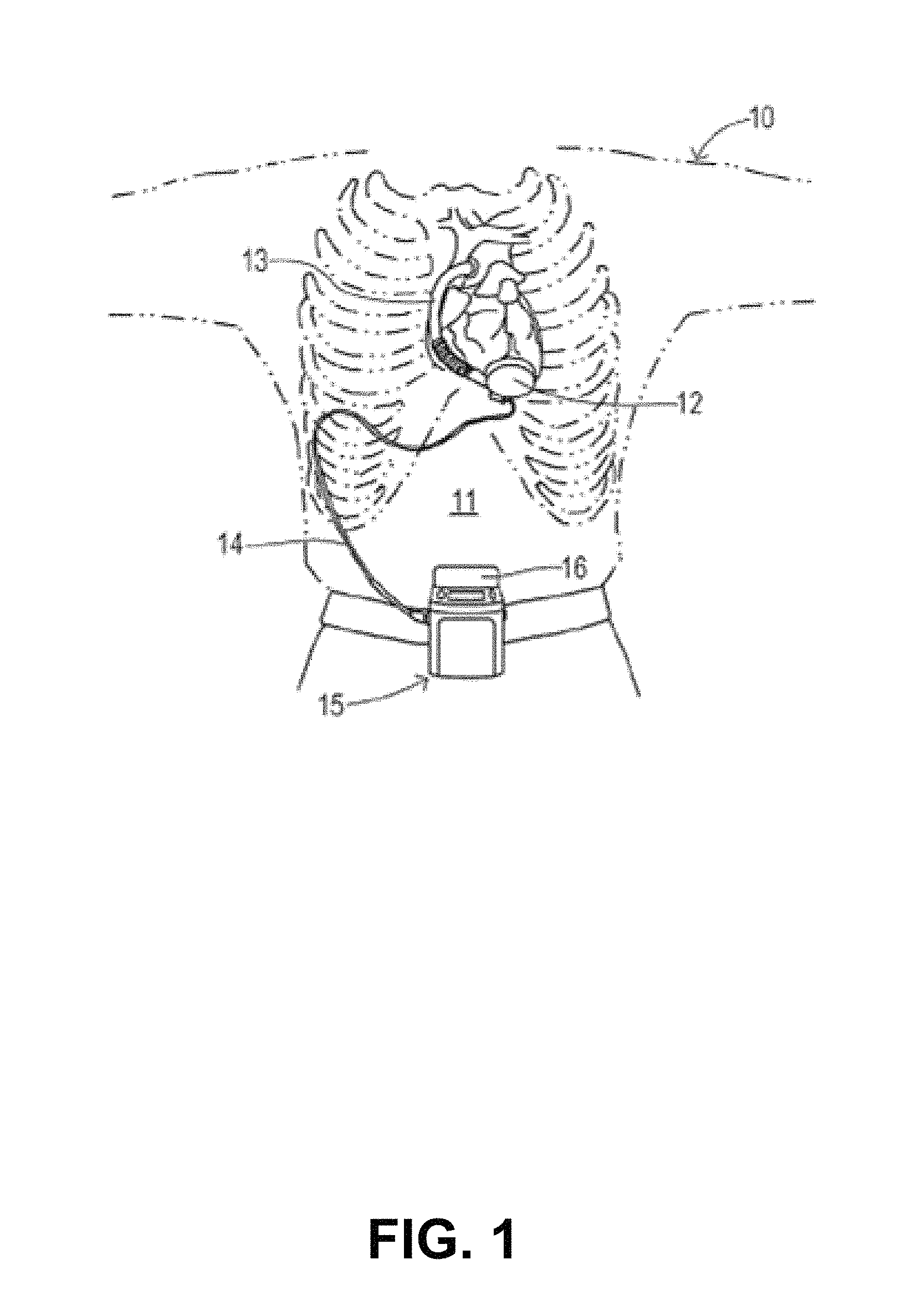
FIG. 1 is a diagram of an implantable pump as one example of a rotary machine employing the present invention.
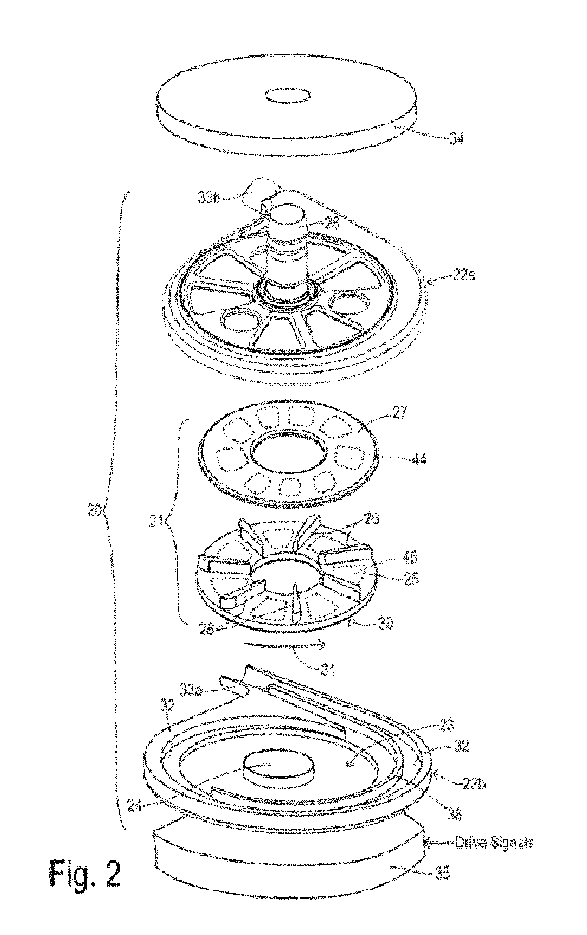
FIG. 2 is an exploded, perspective view of the exemplary centrifugal pump of FIG. 1.
FIG. 3 is a cross-sectional view of the exemplary pump of FIG. 1, illustrating the impeller levitated at a first balanced position generally centered within the pumping chamber in accordance with aspects of the invention.
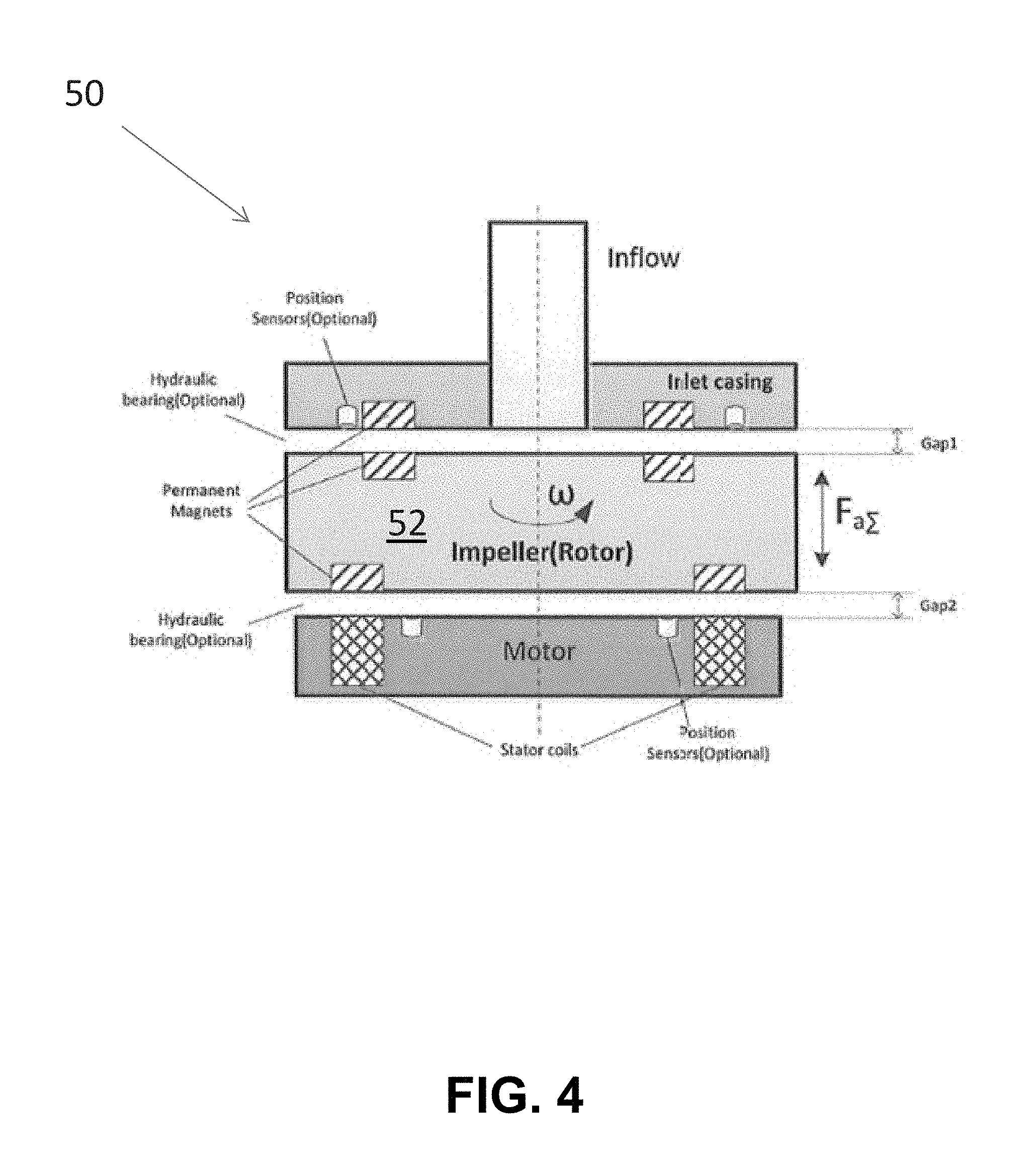
FIG. 4 is a schematic view of the exemplary pump of FIG. 1, illustrating the impeller levitated eccentrically in the pump chamber by the main bearing components.
FIG. 5 is a block diagram of a pump control system in accordance with the invention.
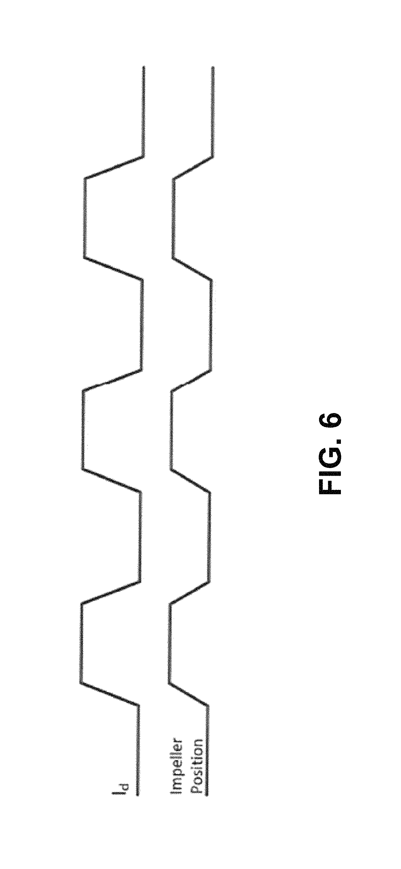
FIG. 6 is a line chart depicting the method of controlling the impeller position in accordance with the invention.
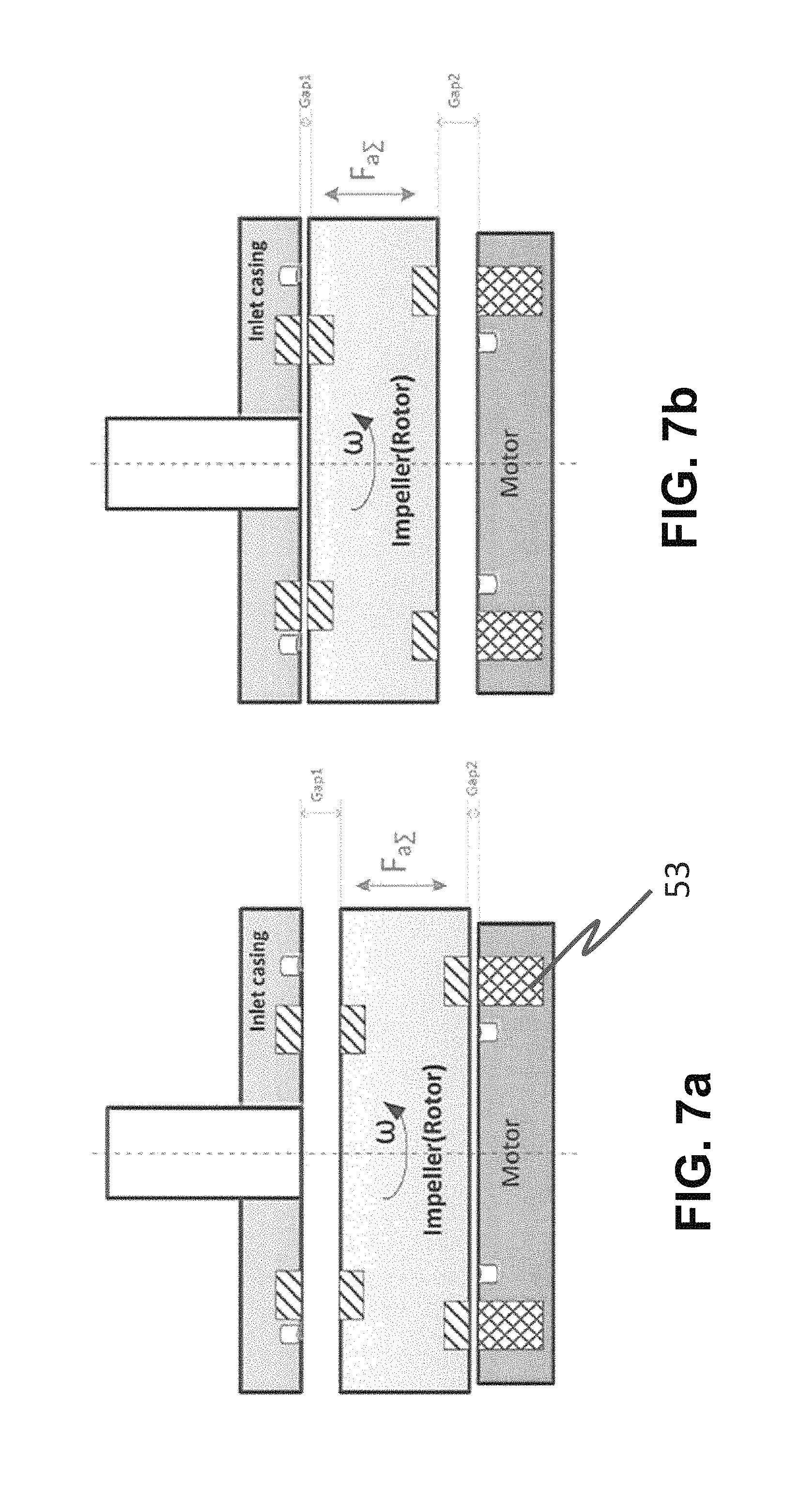
FIG. 7a is a schematic view of the pump of FIG. 1, illustrating the impeller moved to another eccentric position at the bottom of the pump chamber.
FIG. 7b is a schematic view of the pump of FIG. 1, illustrating the impeller moved to yet another eccentric position at the top of the pump chamber.
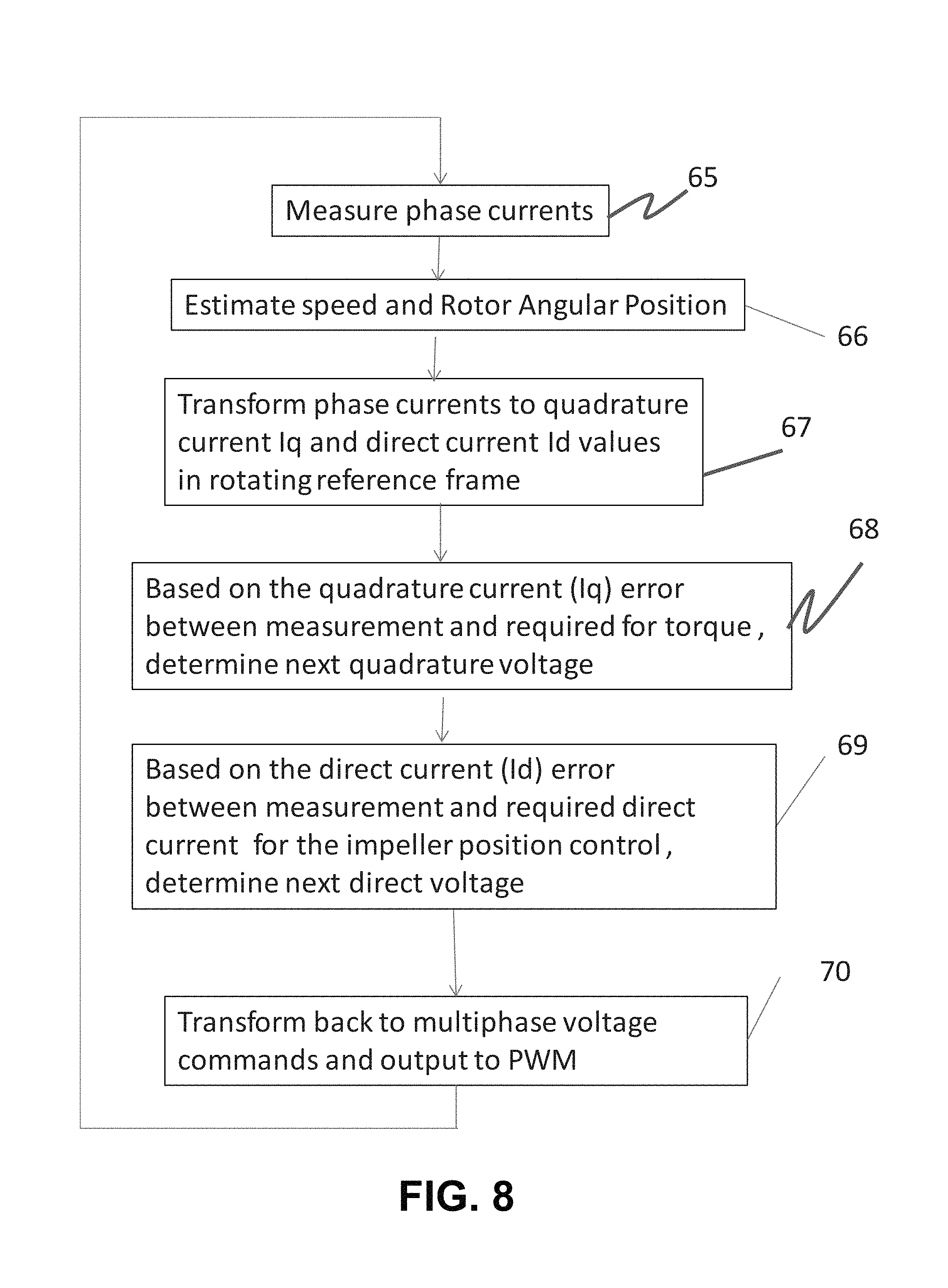
FIG. 8 is a flowchart showing a method of controlling impeller position in accordance with the invention.
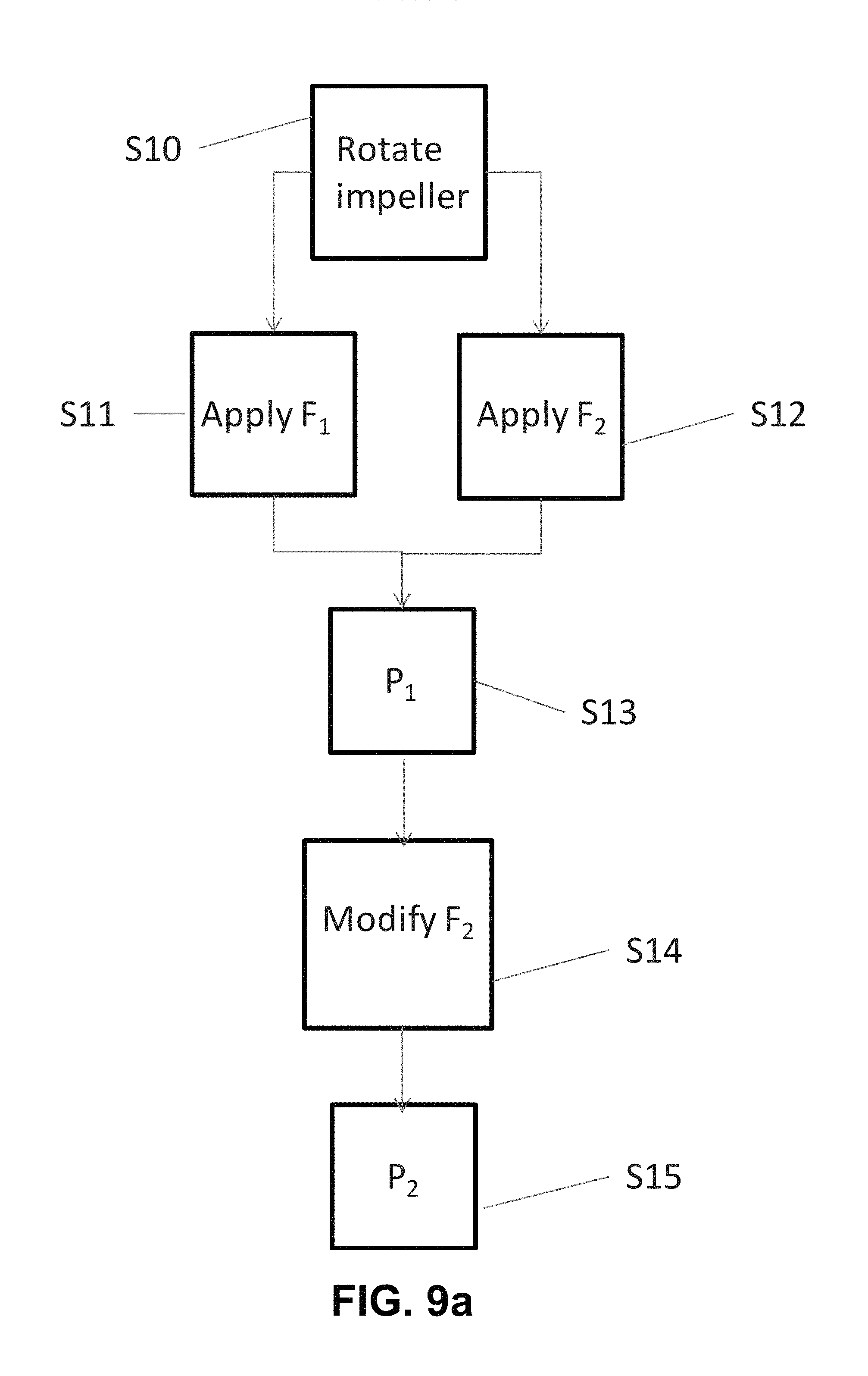
FIG. 9a is a flowchart showing a method of controlling impeller position in accordance with the invention.
FIG. 9b is a line chart depicting a method for moving the impeller between two balanced positions in accordance with aspects of the invention.
FIG. 10 is a flowchart showing a method of controlling impeller position during start-up of the pump in accordance with the invention.
FIG. 11 is a cross-sectional view of an exemplary centrifugal flow pump in accordance with aspects of the invention, illustrating electromagnetic bearings to supplement the stator assembly positioning control.
FIG. 12 is a cross-sectional view of an axial flow pump in accordance with aspects of the invention, the axial flow pump including mechanical bearings.
FIG. 13 is a perspective view of the impeller of FIG. 12, with arrows depicting the direction of translation in accordance with the invention.
FIG. 14 is a cross-sectional view of another axial flow pump in accordance with aspects of the invention, the axial flow pump including mechanical bearings.
FIG. 15 is a cross-sectional view of another axial flow pump in accordance with aspects of the invention, the axial flow pump including passive magnetic and hydrodynamic bearings.
DETAILED DESCRIPTION OF THE INVENTION
Reference will now be made in detail to the preferred embodiments of the invention, examples of which are illustrated in the accompanying drawings. While the invention will be described in conjunction with the preferred embodiments, it will be understood that they are not intended to limit the invention to those embodiments. On the contrary, the invention is intended to cover alternatives, modifications and equivalents, which may be included within the spirit and scope of the invention as defined by the appended claims.
For convenience in explanation and accurate definition in the appended claims, the terms "up" or "upper", "down" or "lower", "inside" and "outside" are used to describe features of the present invention with reference to the positions of such features as displayed in the figures.
In many respects the modifications of the various figures resemble those of preceding modifications and the same reference numerals followed by subscripts "a", "b", "c", and "d" designate corresponding parts.
As used herein, "gap" generally refers to the secondary flow gaps around the impeller as would be understood by one of skill in the art. The primary flow is through the impeller blade regions. The secondary flow gaps are the other areas of fluid, generally around the impeller. In some respects, the secondary flow gaps are between the impeller and the housing wall and define the hydrodynamic bearing.
The term "machine-readable medium" includes, but is not limited to portable or fixed storage devices, optical storage devices, wireless channels and various other mediums capable of storing, containing or carrying instructions and/or data. A code segment or machine-executable instructions may represent a procedure, a function, a subprogram, a program, a routine, a subroutine, a module, a software package, a class, or any combination of instructions, data structures, or program statements. A code segment may be coupled to another code segment or a hardware circuit by passing and/or receiving information, data, arguments, parameters, or memory contents. Information, arguments, parameters, data, etc. may be passed, forwarded, or transmitted via any suitable means including memory sharing, message passing, token passing, network transmission, etc.
Furthermore, embodiments of the invention may be implemented, at least in part, either manually or automatically. Manual or automatic implementations may be executed, or at least assisted, through the use of machines, hardware, software, firmware, middleware, microcode, hardware description languages, or any combination thereof. When implemented in software, firmware, middleware or microcode, the program code or code segments to perform the necessary tasks may be stored in a machine readable medium. One or more processors may perform the necessary tasks.
Although aspects of the invention will be described with reference to a blood pump, one will appreciate that the invention can be applied to various rotary machines and other types of pumps. The mechanisms and methods of the invention will be described in relation to blood pumps and in particular the ability to adjust the impeller operating position to address performance, such as the attendant risks for thrombus and hemolysis when pumping blood. One will appreciate from the description herein that the invention can be applied broadly to other pumps, rotary machines, and induction motors.
Aspects of the invention enable to the ability to enhance or control the bearing gap. One might wish to increase the bearing gap to adjust the washout rate, lubricate the bearing surfaces, or remove materials (particulates, thrombus, etc.) from the bearing gap. Another use of the invention may be to increase pump efficiency. As is known in the art, the motor efficiency increases as the impeller magnet moves closer to the motor drive coils. Another use of the invention may be to correct impeller malpositioning due to bulk forces or external forces (e.g. bumps or movements of the patient's body). These and other advantages can be achieved without the need for complex control systems in accordance with the invention.
In one embodiment, an electromagnetic force control method is used to change the impeller position and enhance the effective gap between the impeller and the blood chamber. The technique uses the same pump motor stator coils adjust the impeller position as is used to apply a torque to the impeller. No additional control subsystems and components are necessary.
Turning now to the drawings, wherein like components are designated by like reference numerals throughout the various figures, attention is directed to FIG. 1 which depicts an exemplary pump implanted in a heart failure patient.
A typical cardiac assist system includes a pumping unit, drive electronics, microprocessor control unit, and an energy source such as rechargeable batteries and/or an AC power conditioning circuit. The system is implanted during a surgical procedure in which a centrifugal pump is placed in the patient's chest. An inflow conduit is pierced into the left ventricle to supply blood to the pump. One end of an outflow conduit is mechanically fitted to the pump outlet and the other end is surgically attached to the patient's aorta by anastomosis. A percutaneous cable connects to the pump, exits the patient through an incision, and connects to the external control unit.
Various aspects of the implantable pump are similar to those shown and described in U.S. Pat. Nos. 4,528,485; 4,857,781; 5,229,693; 5,588,812; 5,708,346; 5,917,297; 6,100,618; 6,222,290; 6,249,067; 6,268,675; 6,355,998; 6,351,048; 6,365,996; 6,522,093; 7,972,122; 8,686,674; 8,770,945; U.S. Pub. No. 2014/0205467; 2012/0095281; and U.S. patent application Ser. No. 15/041,987, the entire contents of which patents and publications are incorporated herein by this reference for all purposes.
The exemplary system utilizes an implantable pump with contactless bearings for supporting the impeller. Contactless bearings (i.e., levitation) provide a number of potential benefits. Because they reduce rotational friction, theoretically they improve motor efficiency and reduce the risk of introducing particulates into the fluid. In one example, the impeller employs upper and lower plates having magnetic materials (the terminology of upper and lower being arbitrary since the pump can be operated in any orientation). A stationary magnetic field from the upper side of the pump housing attracts the upper plate and a rotating magnetic field from the lower side of the pump housing attracts the lower plate. The forces cooperate so that the impeller rotates at a levitated position within the pumping chamber. Features (not shown) may also be formed in the walls of the pumping chamber to produce a hydrodynamic bearing wherein forces from the circulating fluid also tend to center the impeller. Hydrodynamic pressure grooves adapted to provide such a hydrodynamic bearing are shown in U.S. Pat. No. 7,470,246, issued Dec. 30, 2008, titled "Centrifugal Blood Pump Apparatus," which is incorporated herein for all purposes by reference.
The exemplary impeller has an optimal location within the pumping chamber with a predetermined spacing from the chamber walls on each side. Maintaining a proper spacing limits the shear stress and the flow stasis of the pump. A high shear stress can cause hemolysis of the blood (i.e., damage to cells). Flow stasis can cause thrombosis (i.e., blood clotting).
With continued reference to FIG. 1, a patient is shown in fragmentary front elevational view. Surgically implanted either into the patient's abdominal cavity or pericardium 11 is the pumping unit 12 of a ventricular assist device. An inflow conduit (on the hidden side of unit 12) pierces the apex of the heart to convey blood from the patient's left ventricle into pumping unit 12. An outflow conduit 13 conveys blood from pumping unit 12 to the patient's ascending aorta. A percutaneous power cable 14 extends from pumping unit 12 outwardly of the patient's body via an incision to a compact control unit 15 worn by patient 10. Control unit 15 is powered by a main battery pack 16 and/or an external AC power supply, and an internal backup battery. Control unit 15 includes a commutator circuit for driving a motor within pumping unit 12.
In various embodiments, the commutator circuit and/or various electronics may be on the implanted side of the system. For example, various electronics may be positioned on-board the pump or in a separate hermetically sealed housing. Among the potential advantages of implanting electronics is the ability to control the pump even when communication is lost with the control unit 15 outside the body.
FIG. 2 shows exemplary centrifugal pump unit 20 used in the system of FIG. 1. The pump unit 20 includes an impeller 21 and a pump housing having upper and lower halves 22a and 22b. Impeller 21 is disposed within a pumping chamber 23 over a hub 24. Impeller 21 includes a first plate or disc 25 and a second plate or disc 27 sandwiched over a plurality of vanes 26. Second disc 27 includes a plurality of embedded magnet segments 44 for interacting with a levitating magnetic field created by levitation magnet structure 34 disposed against housing 22a. For achieving a small size, magnet structure 34 may comprise one or more permanent magnet segments providing a symmetrical, static levitation magnetic field around a 3600 circumference. First disc 25 also contains embedded magnet segments 45 for magnetically coupling with a magnetic field from a stator assembly 35 disposed against housing 22b. Housing 22a includes an inlet 28 for receiving blood from a patient's ventricle and distributing it to vanes 26. Impeller 21 is preferably circular and has an outer circumferential edge 30. By rotatably driving impeller 21 in a pumping direction 31, the blood received at an inner edge of impeller 21 is carried to outer circumferential 30 and enters a volute region 32 within pumping chamber 23 at an increased pressure. The pressurized blood flows out from an outlet 33 formed by housing features 33a and 33b. A flow-dividing guide wall 36 may be provided within volute region 32 to help stabilize the overall flow and the forces acting on impeller 21.
FIG. 3 shows an exemplary pump 10 similar to the pump shown in FIG. 2. FIG. 3 shows impeller 21 located in a balanced position. The balanced position sometimes refers to the position the impeller naturally stabilizes or finds equilibrium during operation. In the exemplary embodiment, the balanced position is at or near the center of the pump chamber. In the balanced position, the forces acting on the impeller are generally balanced to stabilize the impeller. As one will understand from the description above that the hydrodynamic forces on the impeller will change as the rotational speed of the impeller changes. In turn, the magnetic attractive forces on the impeller will change as the impeller moves closer to or away from the magnet structure 34 and stator assembly 35. Accordingly, the impeller generally finds a new balanced position as the rotational speed changes.
As will be described below, however, aspects of the invention are directed to moving the impeller or changing the balanced position for each given rotational speed. For example, the impeller position control mechanisms to be described facilitate moving the impeller axially (up or down) without changing the rotational speed and all other. This has the effect of enabling movement of the impeller independent of rotor speed. An advantage of this technique is that rotor speed can be determined in normal course (e.g. by a physician based on the patient's physiological needs) without concern for changing the impeller position. Conversely, the impeller position can be changed without affecting pumping throughput.
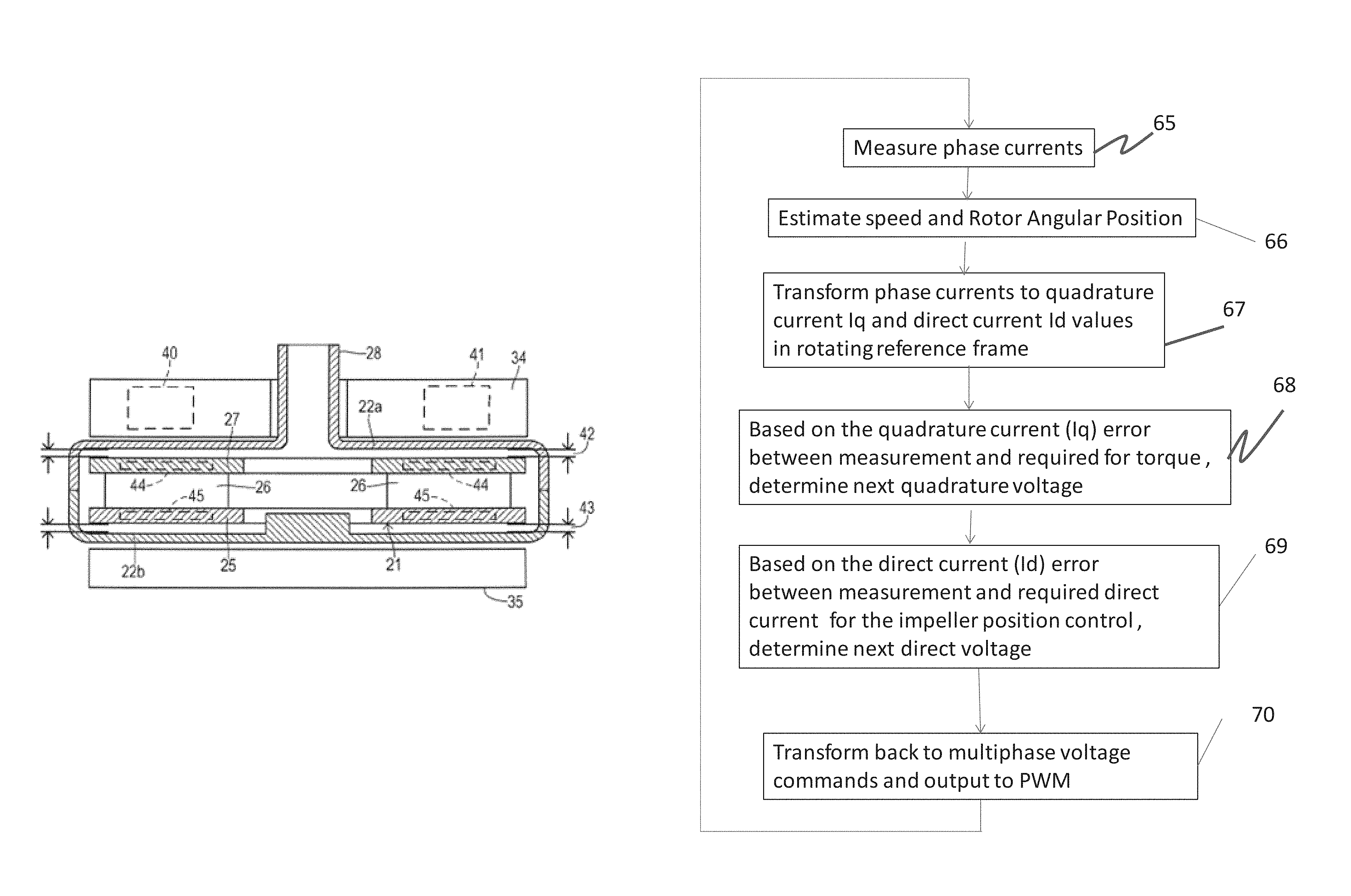
FIG. 3 shows impeller 21 located at or near a centered position wherein disc 27 is spaced from housing 22A by a gap 42 and impeller disc 25 is spaced from housing 22B by a gap 43. In the exemplary embodiment, the center position is chosen as the balanced or balanced position to ensure substantially uniform flow through gaps 42 and 43. During pump operation, the balanced position is maintained by the interaction of (a) attractive magnetic forces between permanent magnets 40 and 41 in levitation magnet structure 34 with imbedded magnetic material 44 within impeller disc 27, (b) attractive magnetic forces between stator assembly 35 and embedded magnet material 45 in impeller disc 25, and (c) hydrodynamic bearing forces exerted by the circulating fluid which may be increased by forming hydrodynamic pressure grooves in housing 22 (not shown). By using permanent magnets in structure 34 a compact shape is realized and potential failures associated with the complexities of implementing active levitation magnet control are avoided. To properly balance impeller 21 at the centered position, however, and because other forces acting on impeller 21 are not constant, an active positioning control may be desired. In particular, the hydrodynamic forces acting on impeller 21 vary according to the rotational speed of impeller 21. Furthermore, the attractive force applied to impeller 21 by stator assembly 35 depends on the magnitude of the magnetic field and the angle by which the magnetic field leads the impellers magnetic field position.
The structures and methods for controlling the motor will now be described with references to FIGS. 4 to 6.
FIG. 4 shows the main structure of an exemplary centrifugal pump 50 similar to that shown in FIG. 3. It is understood that other pump configurations may be employed, including various combinations of permanent magnets, motor stator windings, and hydrodynamic bearings. In the exemplary embodiment, the rotor is formed as an impeller and driven by a motor. The impeller is also levitated by the combined force F.sub.a.SIGMA., which can be expressed as the following equation: F.sub.a.SIGMA.=F.sub.hdb+F.sub.pm+F.sub.em
Where,
F.sub.a.SIGMA. is the combined force to levitate the impeller
F.sub.hdb is the combination of hydrodynamic forces from the inlet side bearing, the motor side bearing, or both
F.sub.pm is the combination of permanent magnet attraction forces
F.sub.em is the magnetic attraction force generated from the motor
When the impeller is stabilized, F.sub.a.SIGMA. should be equal to zero. Usually F.sub.em can be controlled through the electronic system to adjust the impeller position since all the others are the fixed configurations as the passive mode. Therefore, the basic design concept of this invention is to apply the motor vector control (FOC) to control the force F.sub.em so that the impeller position can be adjusted while rotating only using one set of motor coil and drive system. In such way, there is no additional cost in the pump structure.
FIGS. 5 to 6 illustrate a method for controlling voltages applied to a stator in order to provide a desired rotation for a permanent magnet rotor (e.g. the impeller) 52 is a field oriented control (FOC) algorithm, which is also known as vector control. It is known in FOC that the stator magnetic field should generally lead the impeller position by 90.degree. for maximum torque efficiency. The magnitude of the attractive force on the impeller is proportional to the magnitude of the phase currents in the stator. Phase current is adjusted by the FOC algorithm according to torque demands for the pump. Since the commutation angle is typically fixed at 90.degree., the resulting attractive force varies according to torque output from the pump. The exemplary technique varies the I.sub.d current which creates magnetic flux responsible for attracting the impeller. This provides a convenient and accurate mechanism to create a controlled impeller attractive force.
At any particular combination of the (1) magnitude of the phase current and (2) the speed of the impeller, modifying the commutation angle for generating the phase voltages can change the attractive force generated by the stator thereby affecting the impeller balance. In turn, the impeller moves until it settles at a new balanced position where the hydrodynamic forces and magnetic forces are balanced.
FIGS. 5, 6, 7a, and 7b illustrate an exemplary system in accordance with aspects of the invention. Based on the principle of motor vector control, the torque current that is usually called quadrature current (I.sub.q current) and stator coil flux current that is called direct current (I.sub.d current) can be decoupled and controlled independently. The quadrature current I.sub.q current is used to control the impeller rotational speed. The direct I.sub.d current controls the magnetic flux of electromagnetic coils.
In accordance with the invention, I.sub.d current is utilized to control the impeller position by enhancing or weakening the magnetic flux between impeller (rotor) and motor stator coils to adjust the attraction force F.sub.em. This in turn changes the impeller position (shown in FIG. 6).
In one embodiment, the impeller position control technique is implemented as an open loop control without impeller position sensors. In one embodiment, impeller position control technique is implemented as a closed loop control with impeller position sensors.
In order to ensure proper positioning, active monitoring and control of the impeller position has been employed in the exemplary embodiment by adjusting the stationary magnetic field. However, position sensors and an adjustable magnetic source occupy a significant amount of space and add to the complexity of a system.
Accordingly, the use of sensors may depend on the design requirements. Suitable sensors may include, but are not limited to, Hall-effect sensors, variable reluctance sensors, and accelerometers.
In one embodiment using the open loop control, the impeller is controlled by periodically alternating the position from one side to another (e.g. from inlet side to motor side) by modulating the I.sub.d current as shown in FIG. 6. In this manner, the side gaps (Gap 1 and Gap 2) as shown in FIGS. 7a and 7b can be increased or decreased.
The position control technique can be implemented into the hardware and/or software of the system. Referring to FIG. 5, by example, the controller may employ FOC to supply a multiphase voltage signal to the stator assembly 53. The exemplary stator assembly is a three-phase stator. Individual phases a, b, and c and currents I.sub.a, I.sub.b, and I.sub.c may be driven by an H-bridge inverter functioning as a commutation circuit driven by a pulse width modulator (PWM) circuit. An optional current sensing circuit associated with the inverter measure instantaneous phase current in at least two phases providing current signals designated I.sub.a and I.sub.b. A current calculating block receives the two measured currents and calculates a current I.sub.c corresponding to the third phase. The measured currents are input to Vector Control (FOC) block 54 and to a current observer block (not shown) which estimates the position and speed of the impeller. The impeller position and speed are input to the FOC block from speed control block 55 and position control block 56. A target speed or revolutions per minute (rpm) for operating the pump is provided by a conventional physiological monitor to FOC block 54. The target rpm may be set by a medical caregiver or determined according to an algorithm based on various patient parameters such heart beat, physiological needs, suction detection, and the like. FOC block 54 and drive electronics 57 generate commanded voltage output values Va, Vb, and Vc. The Va, Vb, and Vc commands may also be coupled to the observer block for use in detecting speed and position.
The exemplary system differs from conventional configurations inasmuch as the FOC block and electronics are configured to alter the field oriented control algorithm so that a direct current (Id) can be varied independently and generate a desired attractive force.
In one embodiment, the invention proceeds according to a method as shown in FIG. 8 which highlights a portion of the impeller position control with the field oriented control algorithm. Thus, in step 65 the phase currents are measured. Based on the measured phase currents, the current speed and rotor angle of the impeller are estimated in step 66. Based on the measured rotor angle in step 66, the phase currents are transformed into a two-axis coordinate system to generate quadrature current (I.sub.q current) and direct current (I.sub.d) values in a rotating reference frame in step 67. Quadrature current is used to control the torque to rotate the impeller and direct current is used to control the attraction force between rotor and stator to control the impeller position. In step 68, the next quadrature voltage is determined by the quadrature current error between the quadrature current transformed from step 67 and the required current for impeller rotation. In step 69, the next direct voltage is determined by the direct current error between the direct current transformed from step 67 and the required current for the attraction force alternation to control the impeller position. In step 70, the quadrature and direct voltages are transformed back to the stationary reference frame in order to provide the multiphase voltage commands which are output to the PWM circuit.
FIG. 9a is a flowchart showing another method of operating a rotary machine in accordance with the invention. The method includes operating the pump to rotate the impeller by applying a rotating magnetic field in step S10. During operation the impeller is levitated and positioned at a balanced position (P.sub.1) by a balancing of forces. As described above, in an exemplary embodiment the impeller is levitated by the combination of hydrodynamic forces F.sub.1 and other bearing forces F.sub.2 (e.g. stator attractive force, passive magnetic forces, and/or bulk forces like gravity) in steps S11 and S12. Next, at least one of the forces, F.sub.2, is modified to place the impeller out of balance in step S14. The impeller moves to a new position, P.sub.2, where the forces are once again balanced in step S15.
As described above, the impeller is moved from the first balanced position (P.sub.1) to the second balanced position (P.sub.2) by applying an attractive force or modifying (increasing or decreasing) an existing attractive force on the impeller. In various embodiments, the attractive force modulation is substantially continuously applied to hold the impeller in the second balanced position. In various embodiments, the attractive force modulation is applied periodically (e.g. as pulses) to hold the impeller in the second balanced position. In various embodiments, the attractive force modulation is applied as a single pulse to move the impeller in the second balanced position. The second balanced position can be configured so the impeller remains in the second balanced position in a stable manner even when the attractive force is removed.
FIG. 9b illustrates an exemplary method for moving the impeller between two balanced positions in accordance with aspects of the invention. In this example, a permanent magnet arrangement is contemplated whereby the two balanced positions are naturally a product of the permanent magnet arrangement, so that the above-mentioned attractive force modulation may not necessarily be needed or required to hold the impeller in a particular balanced position. Rather, a single (or series) pulse may be applied to "push" the impeller from one stable position to another. For example, as shown in FIG. 9b, the impeller is initially, at a time t1, at a stable balanced position A. At a time t2 a pulse of duration (t3-t2) is applied to push the impeller to a new, stable balanced position B. In practice, the impeller may be pushed between stable balanced position A and stable balanced position B in a manner as needed or desired, such as shown in FIG. 9b. Advantageously, such an implementation may save energy and improve pump efficiency. In one embodiment, one of the two stable positions may be relatively close to the inlet of the above mentioned centrifugal pump unit, and another relatively close to the motor.
Turning to FIG. 10, in one embodiment, the impeller position control technique is used to facilitate start-up of the pump. In step S20, the exemplary pump is configured so the impeller rests against the inlet side (top of the housing) when the impeller is not rotating. In a typical pump with hydrodynamic forces alone, or in combination with magnetic forces, the impeller is levitated away from the wall as it rotates. The blood entrained in the gap between the impeller and the house creates hydrodynamic pressure; however, the impeller must be rotating at a sufficient speed to create the hydrodynamic pressure. Until the minimum speed is met, the impeller rubs against the housing wall. In the exemplary pump, by contrast, the impeller is pulled away from the wall prior to, or just after, rotation begins thereby eliminating the deleterious effects of friction. The impeller is pulled away from the wall by applying a force, F, as described above in step S21. For example, the commutation angle may be modified to exert an attractive force. Referring to FIG. 7b, by example, the pump can be configured so the impeller rests at the inlet side. By applying an attractive force to the motor side the impeller moves down from the top wall. In step S22, the regular start-up sequence is initiated after the impeller is removed from the wall.
FIG. 11 shows a rotary machine in accordance with another embodiment making use of electromagnets. Pump 100 in FIG. 11 is similar in various respects to pump 10 in FIG. 3. In the exemplary embodiment, however, pump 100 includes an active electromagnetic (EM) system 1010. The EM force generated by electromagnets is used primarily or adjunctively to move the impeller. Exemplary electromagnets 101 comprise iron cores and windings. The EM force is modified in a conventional manner by changing the current applied to the windings. The application of the EM force causes the impeller to move to position P.sub.E2. One will appreciate that the EM force can overpower hydrodynamic and passive magnetic forces present in the system. Accordingly, the EM structure must be dimensioned and configured to apply a relatively balanced force. An advantage of using electromagnets over the existing stator assembly is that there is relatively greater positional control over the impeller. By contrast, as described above, the phase currents typically cannot be used as the primary variable to adjust the axial attractive force on the impeller. A disadvantage of this embodiment is the need to provide an entirely separate EM system. This may not be an issue with large industrial rotary machines, but many types of motors have restrictive form factors. For example, implanted pumps must be relatively small in order to address a wider patient population.
FIGS. 12 and 13 illustrate another implantable pump in accordance with the invention. Pump 200 is similar in various respects to pumps 10 and 100 described above except pump 200 is an axial flow pump. Blood flows from in through inlet 201 and out through outlet 202 in a generally linear, axial direction. Pump 200 includes an impeller 210 having blades for moving blood through the pump housing and imparting kinetic energy in the fluid.
Impeller 210 is fixed within the housing by ball-and-cup bearings 212 and 214. The ball-and-cup bearings are closely toleranced and generally fix the impeller in a specific position. However, the exemplary bearings are lubricated and washed by the blood flow around the impeller. Accordingly, there is some fluid between the ball and cup surfaces.
Torque is applied to the impeller by a stator assembly 205. The stator assembly 205 includes windings and is driven using a FOC algorithm in a similar manner to the stator assemblies described above. In practice, the impeller position is adjusted proceeding according to the method shown in FIG. 9. Using the FOC technique described above the impeller is rotated in the pump housing. At a desired time the I.sub.d current is modulated to adjust the attractive force on the impeller in the axial direction. As long as the attractive force is sufficient to squeeze blood out from a respective bearing gap, the impeller will move axially towards inlet 201 or outlet 202. The bearing gaps of pump 200 are relatively small compared to Gap 1 and Gap 2 of pump 50 in FIG. 4. However, even relatively small impeller movement may be beneficial to enable control of the bearing gaps.
FIG. 14 illustrates another pump 300 similar to pump 200. Pump 300 includes an impeller fixed between two mechanical bearings 212 and 214. Pump 300 is slightly different than pump 200 because the outlet extends at an angle from the inlet. Pump 300 is configured in a relatively compact design compared to pump 200 including a relatively smaller stator assembly; however, the same general principles can be applied to control the motor and adjust the impeller position.
FIG. 15 is a cross-sectional view of another pump 400 similar to pumps 200 and 300, except pump 400 is an axial flow pump with non-contact bearings. Pump 400 includes a pump housing having an inlet 401 and outlet 402. An impeller 411 is positioned within a pump chamber for imparting flow to the blood fluid within the housing. The impeller is entirely formed of a magnetic material which is driven by interaction with a stator assembly 405.
Impeller 411 is stabilized in the pump chamber by a combination of hydrodynamic and passive magnetic forces. Impeller 411, which is a magnetic material, interacts with the magnetic material in stator assembly 405 to provide an axial centering force. A pump ring 452 with a chamfer surface is positioned at the leading end of the impeller to create hydrodynamic stabilization forces in the axial direction (left to right) and radial direction (up and down on page). A permanent magnet ring 450 is provided at the trailing edge of the impeller is oriented with a north pole facing a north pole of the impeller. This arrangement creates an axial bias force to push the impeller against the pump ring 452. The magnet ring 450 also provides a radially centering force. Finally, the impeller includes deep hydrodynamic grooves to generate a hydrodynamic pressure force against the inner walls of the pump chamber for radial stabilization.
In operation, the impeller remains stable in the axial and radial directions. There may be some axial movement as the rotational speed of the impeller changes or as a result of other forces (e.g. the native pulse), but generally the impeller remains centered below the stator assembly.
Using the FOC control technique described above, the attractive force of the stator assembly 405 on impeller 411 can be modified. In one embodiment, pump 400 is configured so impeller is eccentric when centered below the stator assembly 405. In this example, increasing the attractive force amounts to an increase in the axial stiffness to resist axial movement. In one embodiment, the attractive force is modified to actually move impeller 411 axially. For example, the impeller can be moved closer to pump ring 452 to squeeze blood out of the gap between impeller 411 and a surface of ring 452. The impeller may also be moved away from ring 452 to increase the blood gap therebetween. In this manner, the impeller position control technique adds an element of active position control otherwise not possible with the passive bearing configuration of pump 400.
Although aspects of the invention have been described in connection with blood pumps, one will appreciate from the description herein that the invention can be applied equally to other types of rotary machines such as washing machines, manufacturing machines, computer drives, and more.
The foregoing descriptions of specific embodiments of the present invention have been presented for purposes of illustration and description. They are not intended to be exhaustive or to limit the invention to the precise forms disclosed, and obviously many modifications and variations are possible in light of the above teaching. The embodiments were chosen and described in order to best explain the principles of the invention and its practical application, to thereby enable others skilled in the art to best utilize the invention and various embodiments with various modifications as are suited to the particular use contemplated. It is intended that the scope of the invention be defined by the Claims appended hereto and their equivalents.
* * * * *
References
D00000
D00001
D00002
D00003
D00004
D00005
D00006
D00007
D00008
D00009
D00010
D00011
D00012

D00013
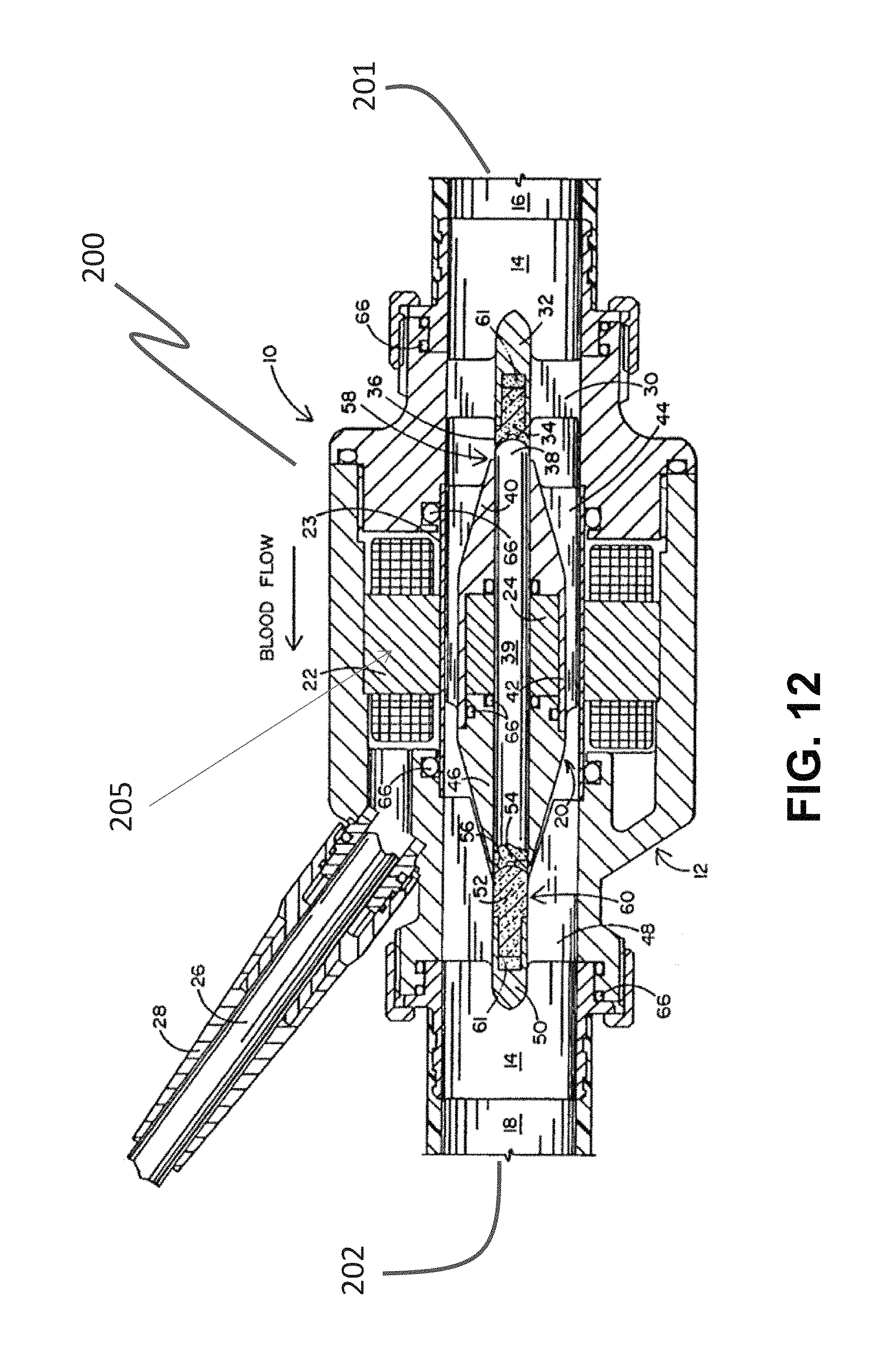
D00014
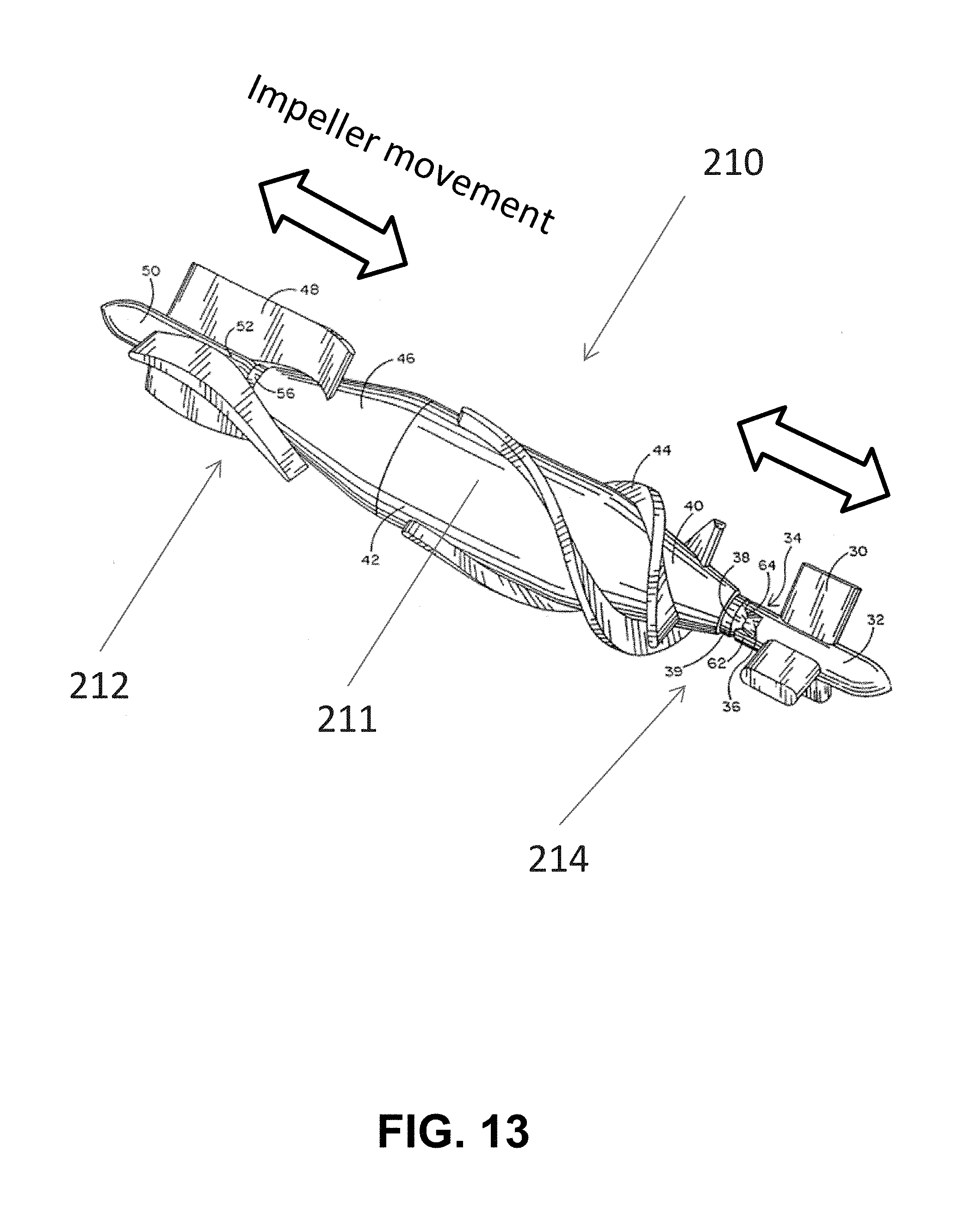
D00015
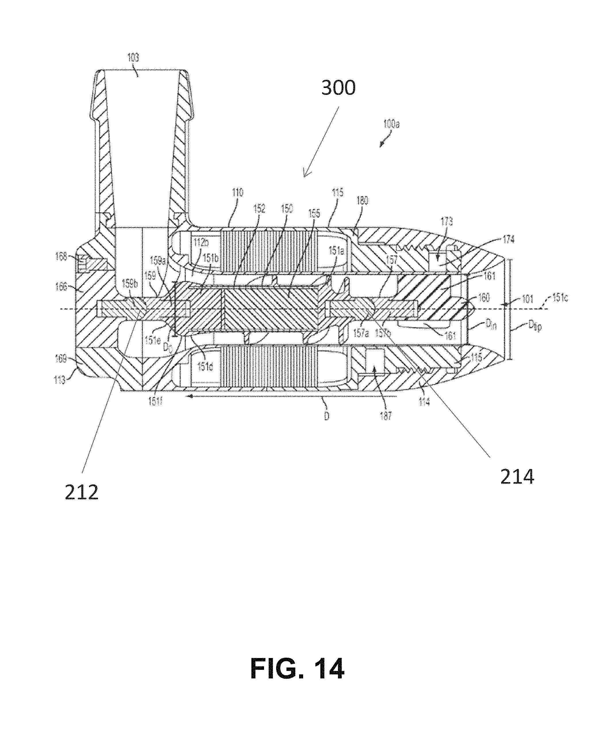
D00016

XML
uspto.report is an independent third-party trademark research tool that is not affiliated, endorsed, or sponsored by the United States Patent and Trademark Office (USPTO) or any other governmental organization. The information provided by uspto.report is based on publicly available data at the time of writing and is intended for informational purposes only.
While we strive to provide accurate and up-to-date information, we do not guarantee the accuracy, completeness, reliability, or suitability of the information displayed on this site. The use of this site is at your own risk. Any reliance you place on such information is therefore strictly at your own risk.
All official trademark data, including owner information, should be verified by visiting the official USPTO website at www.uspto.gov. This site is not intended to replace professional legal advice and should not be used as a substitute for consulting with a legal professional who is knowledgeable about trademark law.