Methods To Avoid Over-developed Aluminized Coatings During Hot Stamping Line Stoppages
Chiriac; Constantin ; et al.
U.S. patent application number 16/240930 was filed with the patent office on 2020-07-09 for methods to avoid over-developed aluminized coatings during hot stamping line stoppages. This patent application is currently assigned to Ford Motor Company. The applicant listed for this patent is Ford Motor Company. Invention is credited to Maik Broda, Elizabeth Bullard, Constantin Chiriac, Kyle Fleeger, Jagbir Guron, Torsten Hallfeldt.
| Application Number | 20200216922 16/240930 |
| Document ID | / |
| Family ID | 71104240 |
| Filed Date | 2020-07-09 |


| United States Patent Application | 20200216922 |
| Kind Code | A1 |
| Chiriac; Constantin ; et al. | July 9, 2020 |
METHODS TO AVOID OVER-DEVELOPED ALUMINIZED COATINGS DURING HOT STAMPING LINE STOPPAGES
Abstract
A method of treating a blank is provided. The method includes moving a blank through a first section of a furnace at an inter-critical temperature and through a second section of the furnace at a critical temperature greater than the inter-critical temperature before hot stamping the blank. Movement of the blank from the first section to the second section of the furnace is delayed during a hot stamping line stoppage. The blank is in the first section of the furnace for a first time period and in the second section of the furnace a second time period less than the first time period. Also, the first section of the furnace may have a first length and in the second section of the furnace may have a second length that is less than the first length.
| Inventors: | Chiriac; Constantin; (Windsor, CA) ; Broda; Maik; (Wuerselen, DE) ; Fleeger; Kyle; (Westland, MI) ; Guron; Jagbir; (Dearborn, MI) ; Hallfeldt; Torsten; (Eschweiler, DE) ; Bullard; Elizabeth; (Royal Oak, MI) | ||||||||||
| Applicant: |
|
||||||||||
|---|---|---|---|---|---|---|---|---|---|---|---|
| Assignee: | Ford Motor Company Dearborn MI |
||||||||||
| Family ID: | 71104240 | ||||||||||
| Appl. No.: | 16/240930 | ||||||||||
| Filed: | January 7, 2019 |
| Current U.S. Class: | 1/1 |
| Current CPC Class: | C21D 1/18 20130101; C23C 2/28 20130101; C21D 1/673 20130101; C23C 2/12 20130101; C23C 2/40 20130101; C21D 2221/00 20130101 |
| International Class: | C21D 1/673 20060101 C21D001/673; C21D 1/18 20060101 C21D001/18; C23C 2/12 20060101 C23C002/12; C23C 2/28 20060101 C23C002/28; C23C 2/40 20060101 C23C002/40 |
Claims
1. A method of treating a blank comprising: moving a blank through a first section of a furnace at an inter-critical temperature and through a second section of the furnace at a critical temperature greater than the inter-critical temperature; and hot stamping the blank, wherein movement of the blank from the first section to the second section of the furnace is delayed during a hot stamping line stoppage.
2. The method according to claim 1, wherein the blank is in the first section of the furnace for a first time period and in the second section of the furnace a second time period less than the first time period.
3. The method according to claim 2, wherein the first time period is at least 1.2 times greater than the second time period.
4. The method according to claim 1, wherein the first section of the furnace has a first length and the second section of the furnace has a second length less than the first length.
5. The method according to claim 1, wherein the first length is at least 1.2 times greater than and the second length.
6. The method according to claim 1, wherein the blank is formed from coated press hardenable steel.
7. The method according to claim 1, wherein the blank is formed from aluminized press hardenable steel, the inter-critical temperature is between 725.degree. C. and 825.degree. C., and the critical temperature is above 910.degree. C.
8. The method according to claim 1, wherein the blank is formed from aluminized press hardenable steel, the inter-critical temperature is between 750.degree. C. and 800.degree. C., and the critical temperature is above 920.degree. C.
9. The method according to claim 8, wherein the blank is positioned in the first section of the furnace at the inter-critical temperature for a time period up to 1200 seconds before moving to the second section of the furnace and being hot stamped.
10. The method according to claim 9, wherein the hot stamped blank comprises an inter-diffusion layer with a thickness less than 16 .mu.m.
11. The method according to claim 8, wherein the blank is positioned in the first section of the furnace at the inter-critical temperature for a time period up to 1800 seconds before moving to the second section of the furnace and being hot stamped, and the hot stamped blank comprises an inter-diffusion layer with a thickness less than 16 .mu.m.
12. The method according to claim 8, wherein the blank is positioned in the first section of the furnace at the inter-critical temperature for a time period up to 2400 seconds before moving to the second section of the furnace and being hot stamped, and the hot stamped blank comprises an inter-diffusion layer with a thickness less than 16 .mu.m.
13. The method according to claim 1, wherein: the blank is formed from aluminized press hardenable steel; the blank is in the first section of the furnace during the hot stamping line stoppage for a time period up to 1800 seconds; the blank moves from the first section to the second section and is hot stamped after the hot stamping line stoppage is over; and the hot stamped blank comprises an inter-diffusion layer with a thickness less than 16 .mu.m.
14. The method according to claim 13, wherein the inter-critical temperature is between 725.degree. C. and 825.degree. C., and the critical temperature is between 910.degree. C. and 950.degree. C.
15. The method according to claim 1, wherein: the blank is formed from aluminized press hardenable steel; the inter-critical temperature is between 750.degree. C. and 800.degree. C., and the critical temperature is between 920.degree. C. and 940.degree. C. the blank is in the first section of the furnace during the hot stamping line stoppage for a time period up to 2400 seconds; the blank moves from the first section to the second section and is hot stamped after the hot stamping line stoppage is over; and the hot stamped blank comprises an inter-diffusion layer with a thickness less than 16 .mu.m.
16. A method of treating a plurality of blanks during stoppage of a hot stamping line, the method comprising: heating a first section of a furnace to an inter-critical temperature between 725.degree. C. and 825.degree. C.; heating a second section of the furnace to a critical temperature between 910.degree. C. and 950.degree. C.; and moving a plurality of blanks on a conveyer line through the first section and the second section of the furnace to a hot stamping press and hot stamping the plurality of blanks; wherein: the conveyer line stops moving during stoppage of the hot stamping line such that a subset of blanks in the first section of the furnace do not move into the second section of the furnace; and the conveyer line starts moving after the stoppage of the hot stamping line is over such that the subset of blanks in the first section of the furnace move into and through the second section of the furnace and to the hot stamping press.
17. The method according to claim 16, wherein the plurality of blanks is formed from aluminized press hardenable steel and the subset of blanks hot stamped by the hot stamping press after the stoppage of the hot stamping line is over comprise an inter-diffusion layer thickness less than 16 .mu.m.
18. The method according to claim 17, wherein the stoppage of the hot stamping line is for a time up to 1800 seconds.
19. A method of hot stamping a blank after stoppage of a hot stamping line comprising: heating a blank formed from a coated press hardenable steel in a first section of a roller hearth furnace to an inter-critical temperature for a first time period; heating the blank in a second section of the roller hearth furnace to a critical temperature greater than the inter-critical temperature for a second time period less than the first time period; stopping the blank from moving from the first section to the second section of the roller hearth furnace during stoppage of the hot stamping line; moving the blank from the first section to the second section of the roller hearth furnace after the stoppage of the hot stamping line is over; and hot stamping the blank after it moves through the second section of the furnace, wherein the blank is positioned in the first section of the roller hearth furnace for up to 2400 seconds and the hot stamped blank has an inter-diffusion layer less than 16 .mu.m.
20. The method according to claim 19, wherein the inter-critical temperature is between 725.degree. C. and 825.degree. C., and the critical temperature is above 910.degree. C.
Description
FIELD
[0001] The present disclosure relates to hot forming steels, and particularly, to hot stamping of coated press hardenable steel.
BACKGROUND
[0002] The statements in this section merely provide background information related to the present disclosure and may not constitute prior art.
[0003] Hot stamping and forming parts out of a press hardenable steel (PHS) generally requires heating a PHS blank into the intercritically (e.g., between 750.degree. C. and 850.degree. C.) or austenitic phase region (e.g., above 900.degree. C.) of the steel, hot stamping the PHS blank, and cooling the hot stamped PHS blank such that a hot stamped PHS part with a martensitic microstructure is provided. However, heating the PHS blank into the austenitic phase region results in undesirable oxidation of the PHS. Accordingly, PHS material is typically provided by steel suppliers with an oxidation resistant coating, for example, an aluminum-silicon alloy coating formed by dipping or passing the PHS through a liquid aluminum-silicon alloy bath. Such coated PHS is often referred to as aluminized PHS. Upon heating an aluminized PHS blank, diffusion between the aluminum-silicon alloy coating and the PHS results in at least two layers, one of which is an interdiffusion layer (IDL) between the PHS and an outer aluminized alloy layer. Unfortunately, the IDL affects welding, particularly resistance welding, of a hot stamped part. Also, studies have shown that an IDL with a thickness equal to or greater than 16 micrometers (.mu.m) prevents resistance welding of hot stamped aluminized PHS parts.
[0004] The present disclosure addresses the issues of IDL thickness among other issues related to hot stamping of steels that have an aluminized coating.
SUMMARY
[0005] This section provides a general summary of the disclosure and is not a comprehensive disclosure of its full scope or all of its features.
[0006] In one form of the present disclosure, a method of treating a blank is provided. The method comprises moving a blank through a first section of a furnace at an inter-critical temperature and through a second section of the furnace at a critical temperature greater than the inter-critical temperature; and hot stamping the blank, wherein movement of the blank from the first section to the second section of the furnace is delayed during a hot stamping line stoppage.
[0007] In some aspects of the present disclosure, the blank is in the first section of the furnace for a first time period and in the second section of the furnace a second time period less than the first time period. In such aspects, the first time period is at least 1.2 times greater than the second time period, for example, at least 1.5 times greater or at least 2.0 times greater than the second time period. In the alternative, or in addition to, the first section of the furnace has a first length and the second section of the furnace has a second length less than the first length. For example, in some aspects of the present disclosure, the first length is at least 1.2 times greater than the second length, for example, at least 1.5 times greater or at least 2.0 times greater than the second length.
[0008] In some aspects of the present disclosure, the blank is a coated press hardenable steel and the inter-critical temperature is between 725.degree. C. and 825.degree. C., and the critical temperature is above 910.degree. C. In such aspects, the inter-critical temperature may be between 750.degree. C. and 800.degree. C., and the critical temperature may be above 920.degree. C.
[0009] In some aspects of the present disclosure, the blank is positioned in the first section of the furnace at the inter-critical temperature for a time period up to 1200 seconds before moving to the second section of the furnace and being hot stamped. Also, the hot stamped blank comprises an inter-diffusion layer with a thickness less than 16 .mu.m.
[0010] In other aspects of the present disclosure, the blank is positioned in the first section of the furnace at the inter-critical temperature for a time period up to 1800 seconds before moving to the second section of the furnace and being hot stamped, and the hot stamped blank comprises an inter-diffusion layer with a thickness less than 16 .mu.m.
[0011] In still other aspects of the present disclosure, the blank is positioned in the first section of the furnace at the inter-critical temperature for a time period up to 2400 seconds before moving to the second section of the furnace and being hot stamped, and the hot stamped blank comprises an inter-diffusion layer with a thickness less than 16 .mu.m.
[0012] In some aspects of the present disclosure, the blank is formed from aluminized press hardenable steel, it is in the first section of the furnace during the hot stamping line stoppage for a time period up to 1800 seconds. The blank moves from the first section to the second section and is hot stamped after the hot stamping line stoppage is over and the hot stamped blank comprises an inter-diffusion layer with a thickness less than 16 .mu.m.
[0013] In another form of the present disclosure, a method of treating a plurality of blanks during stoppage of a hot stamping line is provided. The method comprises heating a first section of a furnace to an inter-critical temperature between 725.degree. C. and 825.degree. C., heating a second section of the furnace to a critical temperature between 910.degree. C. and 950.degree. C., moving a plurality of blanks on rollers (e.g. rollers of a roller hearth furnace) through the first section and the second section of the furnace to a hot stamping press, and hot stamping the plurality of blanks. When the rollers stop moving during stoppage of the hot stamping line, a subset of blanks in the first section of the furnace do not move into the second section of the furnace. When the rollers start moving after the stoppage of the hot stamping line is over, the subset of blanks in the first section of the furnace move into and through the second section of the furnace and to the hot stamping press.
[0014] In some aspects of the present disclosure, the plurality of blanks is formed from aluminized press hardenable steel and the subset of blanks hot stamped by the hot stamping press after the stoppage of the hot stamping line is over comprise an inter-diffusion layer thickness less than 16 .mu.m. Also, the stoppage of the hot stamping line is for a time up to 1800 seconds.
[0015] In yet another form of the present disclosure, a method of hot stamping a blank after stoppage of a hot stamping line is provided. The method comprises heating a blank formed from a coated press hardenable steel in a first section of a roller hearth furnace to an inter-critical temperature for a first time period and heating the blank in a second section of the roller hearth furnace to a critical temperature greater than the inter-critical temperature for a second time period less than the first time period. The blank stops moving from the first section to the second section of the roller hearth furnace during stoppage of the hot stamping line. Also, the blank moves from the first section to the second section of the roller hearth furnace after the stoppage of the hot stamping line is over. The blank is hot stamped after it moves through the second section of the furnace. In some aspects of the present disclosure, the blank is positioned in the first section of the roller hearth furnace for up to 2400 seconds and the hot stamped blank has an inter-diffusion layer less than 16 .mu.m. Also, the inter-critical temperature is between 725.degree. C. and 825.degree. C., and the critical temperature is above 910.degree. C.
[0016] Further areas of applicability will become apparent from the description provided herein. It should be understood that the description and specific examples are intended for purposes of illustration only and are not intended to limit the scope of the present disclosure.
DRAWINGS
[0017] In order that the disclosure may be well understood, there will now be described various forms thereof, given by way of example, reference being made to the accompanying drawings, in which:
[0018] FIG. 1 schematically depicts a baseline hot stamping line for producing parts from aluminized press hardenable steel (PHS);
[0019] FIG. 2 graphically depicts a baseline heating schedule (profile) for the hot stamping line in FIG. 1;
[0020] FIG. 3 schematically depicts a hot stamping line for producing parts from aluminized press hardenable steel (PHS) according to the teachings of the present disclosure;
[0021] FIG. 4 graphically depicts a heating profile for the hot stamping line in FIG. 3 according to the teachings of the present disclosure;
[0022] FIG. 5 is a flow chart of a method of treating a blank according to the teachings of the present disclosure;
[0023] FIG. 6 is a flow chart of a method of treating a plurality of blanks during stoppage of a hot stamping line according to the teachings of the present disclosure;
[0024] FIG. 7 is a micrograph of a press hardenable steel (PHS) with an aluminized coating following a baseline heat treatment graphically depicted in FIG. 2;
[0025] FIG. 8A is a micrograph of a PHS with an aluminized coating following 10 minutes of heat treatment at an inter-critical temperature T.sub.IC graphically depicted in FIG. 4 according to the teachings of the present disclosure;
[0026] FIG. 8B is a micrograph of a boron steel with an aluminized coating following 20 minutes of heat treatment at an inter-critical temperature T.sub.IC graphically depicted in FIG. 4 according to the teachings of the present disclosure;
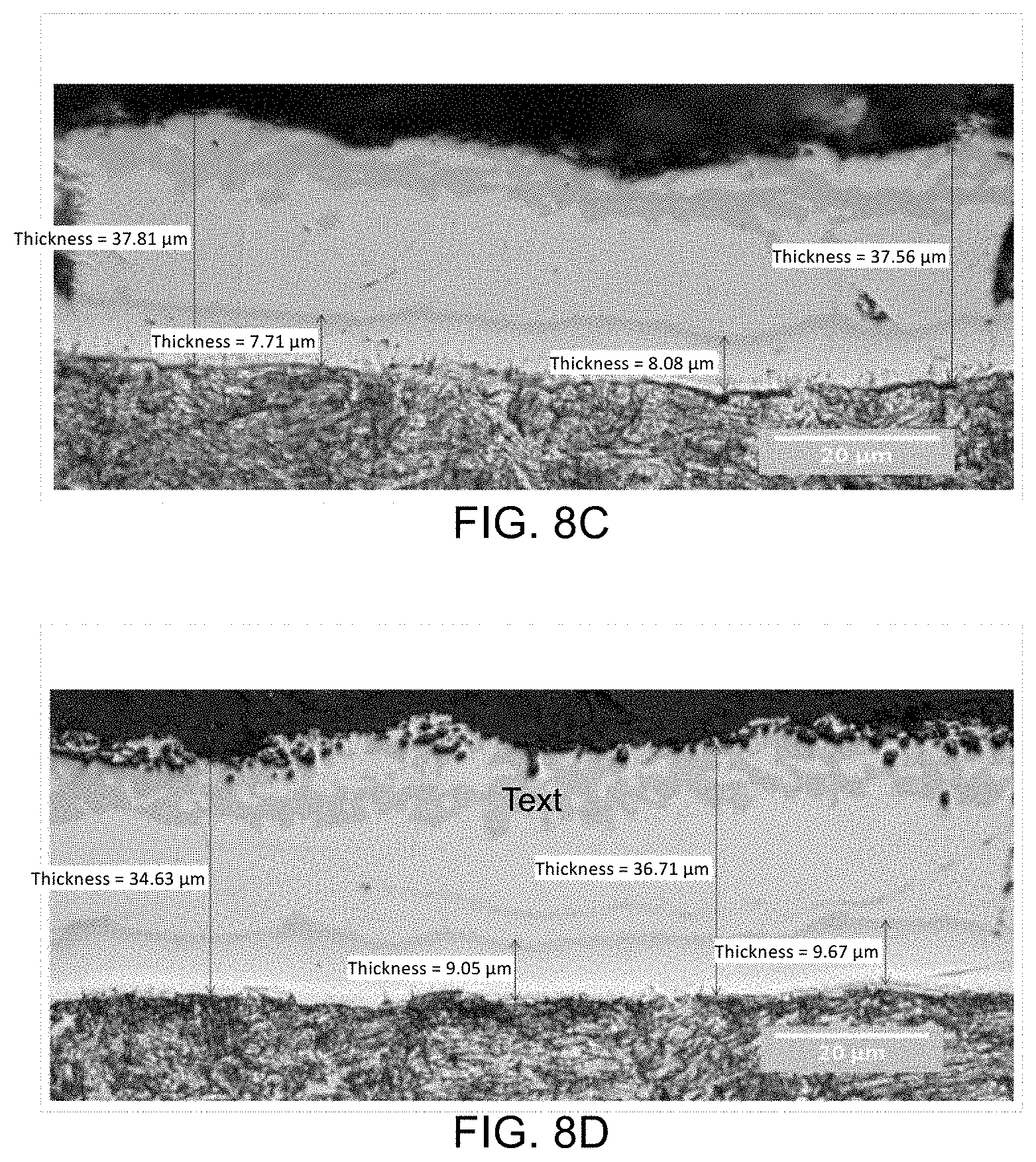
[0027] FIG. 8C is a micrograph of a boron steel with an aluminized coating following 30 minutes of heat treatment at an inter-critical temperature T.sub.IC graphically depicted in FIG. 4 according to the teachings of the present disclosure;
[0028] FIG. 8D is a micrograph of a boron steel with an aluminized coating following 40 minutes of heat treatment at an inter-critical temperature T.sub.IC graphically depicted in FIG. 4 according to the teachings of the present disclosure;
[0029] The drawings described herein are for illustration purposes only and are not intended to limit the scope of the present disclosure in any way.
DETAILED DESCRIPTION
[0030] The following description is merely exemplary in nature and is not intended to limit the present disclosure, application, or uses. It should be understood that throughout the drawings, corresponding reference numerals indicate like or corresponding parts and features. Examples are provided to fully convey the scope of the disclosure to those who are skilled in the art. Numerous specific details are set forth such as types of specific components, devices, and methods, to provide a thorough understanding of variations of the present disclosure. It will be apparent to those skilled in the art that specific details need not be employed and that the examples provided herein, may include alternative embodiments and are not intended to limit the scope of the disclosure. In some examples, well-known processes, well-known device structures, and well-known technologies are not described in detail.
[0031] The present disclosure addresses the issues of interdiffusion layer (IDL) thickness and coating thickness increases due to total furnace time and other issues related to hot stamping steels that have an aluminized coating.
[0032] Referring now to FIG. 1, a baseline hot stamping line 10 for producing parts from aluminized press hardenable steel (PHS) is schematically depicted. In one form of the present disclosure, the baseline hot stamping line 10 generally includes a furnace transfer station 100, a furnace 110, a hot stamping transfer station 120, a hot stamping station 130, and a post-hot stamping transfer station 140. The furnace transfer station 100 transfers aluminized press hardenable steel (PHS) blanks 52 from a stack of aluminized PHS blanks 50 to a conveyer line 112 of the furnace 110. One non-limiting example of the furnace 110 is a roller hearth furnace and the conveyer line 112 is a plurality of rollers. The conveyer line 112 moves the aluminized PHS blanks 52 from a first end 114 to a second end 116 of the furnace 110 where the hot stamping transfer station 120 moves the aluminized PHS blanks 52 to the hot stamping station 130. The aluminized PHS blanks 52 are hot stamped at the hot stamping station 130 to form a hot stamped part 54 and then removed therefrom and moved to a subsequent station (not shown) by the post-hot stamping transfer station 140.
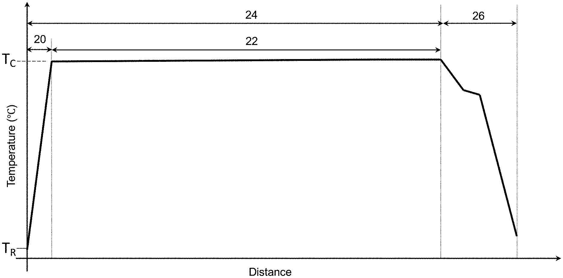
[0033] It should be understood that the thickness of an IDL of an aluminized PHS blank 52 prior to being hot stamped at the hot stamping station 130 is a function of its distance-temperature history (also referred to herein as "distance-temperature profile"). One example of distance-temperature profile for a plurality of aluminized PHS blanks 52 moving along the baseline hot stamping line 10 is graphically depicted in FIG. 2. In such an example, the thickness of the IDL is a function of the temperature T.sub.F of the furnace 110 (also referred to herein as the "furnace temperature"), residence (dwell) time 22 of the aluminized PHS blank 52 in the furnace temperature 110 (also referred to herein as the "dwell time"), and total time 24 of the aluminized PHS blank 52 in the furnace 110 also referred to herein as the "total furnace time"). As used herein, "total furnace time" refers to the time 20 to heat an aluminized PHS blank 52 from room temperature T.sub.R to furnace temperature T.sub.F plus the dwell time 22. It should also be understood that the temperature of the aluminized PHS blank 52 decreases after removal from the furnace 110, during hot stamping at the hot stamping station 130 and during cooling after being hot stamped as graphically depicted by section 26 in FIG. 2.
[0034] Unfortunately, there are issues which cause stoppage of the baseline hot stamping line 10 and thereby result in aluminized PHS blanks 52 exceeding 10 minutes of dwell time 22 at the critical temperature T.sub.C. Also, these delays turn the affected aluminized PHS blanks 52 into production waste because they are rendered unsuitable for further processing as the weldability of the blanks is greatly reduced due to the excessive IDL thickness and porous coating.
[0035] As noted above, an IDL thickness equal to or greater than 16 .mu.m reduces the weldability of the aluminized PHS blank 52 to about zero. As such, current production specifications limit the total furnace time 24 such that the IDL thickness is less than 16 .mu.m. For example, depending on the thickness of the PHS blank 52 and the type of oxidation resistant coating thereon, total furnace time 24 is limited to between 3 to 10 minutes. That is, if aluminized PHS blanks 52 are held in the furnace for a time longer than the prescribed dwell time 22, e.g., due a stoppage of the hot stamping line 10, such aluminized PHS blanks 52 have an IDL thickness greater than 16 .mu.m and are typically scrapped. This time at temperature dependent scrapping of blanks increases the expense of the hot stamping process due to lower material yields, wasted energy, wasted labor, etc.
[0036] Referring now to FIGS. 3 and 4, a hot stamping line 10' and a distance-temperature profile according to the teachings of the present disclosure are shown. Particularly, the furnace transfer station 100 transfers aluminized press hardenable steel (PHS) blanks 52 from a stack of aluminized PHS blanks 50 to the conveyer line 112 of the furnace 110. The conveyer line 112 moves the aluminized PHS blanks 52 from the first end 114 and through a first section 111 of the furnace 110 at an inter-critical temperature T.sub.IC, through a second section 113 of the furnace 110 at a critical temperature T.sub.C, and to the second end 116 of the furnace 110. In some aspects of the present disclosure the first section of the furnace 110 extends from the first end 114 to a divider 115 and the second section of the furnace 113 extends from the divider 115 to the second end 116. In such aspects, the divider 115 may be a baffle, an insulated panel, and the like. In the alternative, the divider 115 may simply represent a change in the power settings of heater element or burners (not shown) positioned in the first section 111 versus the heater elements or burners positioned in the second section 113.
[0037] During movement of the aluminized PHS blank 52 through the first section 111 of the furnace 110, the aluminized PHS steel blank is heated to the inter-critical temperature T.sub.IC during a first transient time period 30 and held at the inter-critical temperature T.sub.IC for a first time period 32. Upon reaching the second section 113 of the furnace 110, the aluminized PHS blank 52 is heated to the critical temperature TC during a second transient time period 34 and held at the critical temperature TC for a second time period 36. When the aluminized PHS blank 52 reaches the second end 116 of the furnace 110 the hot stamping transfer station 120 moves the aluminized PHS blanks 52 to the hot stamping station 130 where it is hot stamped and quenched to form a hot stamped PHS part 54. Thereafter, post-hot stamping transfer station 140 transfers the hot stamped PHS part 54 to a subsequent station (not shown).
[0038] The inter-critical temperature T.sub.IC corresponds to a ferrite plus austenite microstructure in the aluminized PHS blank 52 and the T.sub.C corresponds to a fully austenite microstructure in the aluminized PHS blank 52. The T.sub.C and T.sub.IC are dependent upon the composition of the boron steel. The inter-critical temperature T.sub.IC is sufficiently high such that iron diffuses from the PHS steel into the aluminum-silicon alloy coating to form the eutectic AlSi.sub.10Fe.sub.3 alloy layer in a short time frame (e.g., seconds). The solidification temperature of the eutectic AlSi.sub.10Fe.sub.3 alloy layer is greater than the melting temperature of the aluminum-silicon alloy layer thereby providing a solid (i.e., not liquid) aluminized coating on the aluminized PHS blank 52 as it moves through the furnace 110. Also, the solid eutectic AlSi.sub.10Fe.sub.3 alloy layer is not removed from the aluminized PHS blank 52 and transferred to the conveyer line 112 (e.g., rollers). Heating the aluminized PHS blank 52 to the critical temperature T.sub.C, i.e., heating the aluminized PHS blank 52 into the fully austenitic phase region, followed by cooling and quenching in the region 26 graphically depicted in FIG. 4, transforms the austenite into martensite, martensite plus retained austenite and/or martensite and bainite. Accordingly, the distance-temperature profile graphically depicted in FIG. 4 allows for hot stamping of aluminized PHS blanks 52 such that high strength parts are formed. However, and unlike the distance-temperature profile in FIG. 2, the distance-temperature profile graphically depicted in FIG. 4 allows for the aluminized PHS blanks 52 to remain in the furnace 110 for times greater than 10 minutes without developing an IDL greater than 16 .mu.m. That is, in the event of a stoppage of the hot stamping line 10, diffusion between the PHS steel blank and the eutectic AlSi.sub.10Fe.sub.3 alloy layer at the inter-critical temperature T.sub.IC is such that more than 10 minutes, e.g., more than 30 minutes, is needed before the IDL is equal to or greater than 16 .mu.m as described in greater detail below.
[0039] Referring now referring to FIG. 5, a method 60 of treating a coated PHS blank is provided. At step 62, the method 60 comprises moving a coated PHS blank through a first section of a furnace at an inter-critical temperature and through a second section of the furnace at a critical temperature greater than the inter-critical temperature. The coated PHS blank is hot stamped at step 64 and movement of the blank from the first section to the second section of the furnace is delayed during a hot stamping line stoppage.
[0040] Referring now to FIG. 6, a method 70 of treating a plurality of aluminized PHS blanks during stoppage of a hot stamping line is provided. The method 70 includes heating a first section of a furnace to an inter-critical temperature between 725.degree. C. and 825.degree. C. at step 71 and heating a second section of the furnace to a critical temperature between 910.degree. C. and 950.degree. C. at step 72. A plurality of aluminized PHS blanks are moved through the first section and the second section of the furnace on a conveyor belt to a hot stamping press at step 73. At step 74, the conveyor belt is stopped for a time period up to 40 minutes during a hot stamping line stoppage such that aluminized PHS blanks in the first section of the furnace do not move into the second section of the furnace. The conveyor belt is re-started after the hot stamping line stoppage is over (i.e., the hot stamping line is moving again) at step 75 and the aluminized PHS blanks held in the first section are moved to the second section of the furnace and to a hot stamping station. At step 76, the aluminized PHS blanks held in the first section of the furnace for the time period up to 40 minutes are hot stamped such that hot stamped aluminized PHS parts are provided. It should be understood that the hot stamped aluminized PHS parts formed from the aluminized PHS blanks held in the first section for up to 40 minutes have an IDL thickness of less than 16 .mu.m and thereby can be successfully resistance welded. It should also be understood that the aluminized PHS blanks held in the first section for up to 40 minutes exhibited desired mechanical properties that meet or exceed predefined strength, ductility and/or impact resistance levels.
EXAMPLES
[0041] Samples of aluminized PHS were subjected to distance-temperature profiles as graphically depicted in FIG. 4 for first time periods 32 ranging from 10 to 40 minutes and a second time period 36 equal to 3 minutes. The aluminized PHS material was obtained from the company ARCELORMITTAL.TM. with the coating and PHS compositional ranges shown in Table 1 below. It should be understood that other alloys, for example other PHSs currently available, PHSs currently being developed but not yet commercially available, and PHSs yet to be developed, can be used with the methods disclosed herein and thereby fall within the scope of the teachings of the present disclosure.
TABLE-US-00001 TABLE 1 Element Min. wt. % Max. wt. % Aluminized coating Iron (Fe) 0 .ltoreq.3 Silicon (Si) >0 .ltoreq.10 Aluminum (Al) Balance Boron Steel Aluminum (Al) 0.02 0.06 Boron (B) 0 0.005 Carbon (C) 0.2 0.25 Chromium (Cr) 0 0.35 Copper (Cu) 0 0.2 Manganese (Mn) 1.1 1.4 Molybdenum (Mo) 0 0.35 Nitrogen (N) 0 0.009 Phosphorus (P) 0 0.025 Silicon (Si) 0 0.5 Sulfur (S) 0 0.008 Titanium (Ti) 0.02 0.05 Iron (Fe) Balance plus impurities
[0042] The inter-critical temperature was between 750.degree. C. and 800.degree. C. and the critical temperature was 930.degree. C. The samples were metallographically prepared and examined using optical microscopy and compared to a baseline PHS sample subjected to the distance-temperature profile graphically depicted in FIG. 2 with a dwell time 22 of less than 10 minutes and a critical temperature T.sub.C of 930.degree. C.
[0043] Referring now to FIG. 7, an optical microscopy image (also referred to herein as a "micrograph") of the baseline aluminized coating on the PHS sample subjected to the distance-temperature profile graphically depicted in FIG. 2 with a dwell time 22 of less than 5 minutes is shown. As shown in FIG. 7, the average IDL thickness was about 5 .mu.m and the outer eutectic AlSi.sub.10Fe.sub.3 alloy layer was about 26.6 .mu.m. Given that the IDL thickness is less than 16 .mu.m, such an aluminized PHS sample is suitable for hot stamping and subsequent resistance welding.
[0044] Referring now to FIGS. 8A-8D, micrographs of the PHS samples subjected to the distance-temperature profiles graphically depicted in FIG. 4 are shown. Particularly, FIG. 8A-8D are micrographs of aluminized PHS samples subjected to the inter-critical temperature T.sub.IC for a first time period 32 equal to 10 minutes, 20 minutes, 30 minutes, and 40 minutes, respectively, and the critical temperature T.sub.C for a second time period equal to 3 minutes. The average total coating thickness, average IDL thickness, and average eutectic AlSi.sub.10Fe.sub.3 alloy layer thickness (labeled as "Ave. Coating Thickness") for all of the aluminized PHS samples are provided below in Table 2. As shown in Table 2, all of the aluminized PHS samples subjected to distance-temperature profiles graphically depicted in FIG. 4 had an IDL thickness less than 16 .mu.m, even the aluminized PHS sample subjected to the inter-critical temperature T.sub.IC for 40 minutes. Accordingly, in the event of a stoppage of the hot stamping line 10' (FIG. 3) greater than 10 minutes, aluminized PHS blanks 52 held in the first section 111 of the furnace 110 can be used to produce hot stamped PHS parts 54 and thereby not scrapped.
TABLE-US-00002 TABLE 2 Time in Average Total Ave. IDL Ave. Coating furnace Coating Thickness Thickness (minutes) Thickness (.mu.m) (.mu.m) (.mu.m) FIG. 7 5 31.6 5 26.6 FIG. 8A 10 38.5 6.7 31.8 FIG. 8B 20 36.5 8.1 28.4 FIG. 8C 30 37.7 7.9 29.8 FIG. 8D 40 35.7 9.4 26.3
[0045] In some aspects of the present disclosure, a longer roller hearth furnace compared to traditional roller hearth furnaces used in hot stamping lines is used in the methods disclosed herein. It should be understood that the increase in length of the roller hearth furnace may increase the cost of the roller hearth furnace. However, the additional length of travel at temperature in the longer roller hearth furnace provides an increase in the number of blanks per unit area, feed rate of the blanks through the furnace, the number of temperature zones, and/or the temperature per zone. The inventors have modelled the process in non-roller hearth furnaces which are also within the scope of the present disclosure. The present disclosure is also applicable to zinc-coated press hardened steels.
[0046] The present disclosure reduces the scrap rate, blanks will still experience quality control following an unplanned line stoppage, however the scrap rate has a potential of being 80% with some models placing the scrap rate below 50%, 30%, or 10%. However, even an 80% scrap rate is a marked improvement over the current 100% scrap rate.
[0047] Although the terms first, second, third, etc. may be used to describe various elements, components, regions, layers and/or sections, these elements, components, regions, layers and/or sections, should not be limited by these terms. These terms may be only used to distinguish one element, component, region, layer and/or section, from another element, component, region, layer and/or section. Terms such as "first," "second," and other numerical terms when used herein do not imply a sequence or order unless clearly indicated by the context. Thus, a first element, component, region, layer or section, could be termed a second element, component, region, layer or section without departing from the teachings of the example forms. Furthermore, an element, component, region, layer or section may be termed a "second" element, component, region, layer or section, without the need for an element, component, region, layer or section termed a "first" element, component, region, layer or section.
[0048] As used herein, the phrase at least one of A, B, and C should be construed to mean a logical (A OR B OR C), using a non-exclusive logical OR, and should not be construed to mean "at least one of A, at least one of B, and at least one of C.
[0049] Unless otherwise expressly indicated, all numerical values indicating mechanical/thermal properties, compositional percentages, dimensions and/or tolerances, or other characteristics are to be understood as modified by the word "about" or "approximately" in describing the scope of the present disclosure. This modification is desired for various reasons including industrial practice, manufacturing technology, and testing capability.
[0050] The terminology used herein is for the purpose of describing particular example forms only and is not intended to be limiting. The singular forms "a," "an," and "the" may be intended to include the plural forms as well, unless the context clearly indicates otherwise. The terms "including," and "having," are inclusive and therefore specify the presence of stated features, integers, steps, operations, elements, and/or components, but do not preclude the presence or addition of one or more other features, integers, steps, operations, elements, components, and/or groups thereof. The method steps, processes, and operations described herein are not to be construed as necessarily requiring their performance in the particular order discussed or illustrated, unless specifically identified as an order of performance. It is also to be understood that additional or alternative steps may be employed.
[0051] The description of the disclosure is merely exemplary in nature and, thus, examples that do not depart from the substance of the disclosure are intended to be within the scope of the disclosure. Such examples are not to be regarded as a departure from the spirit and scope of the disclosure. The broad teachings of the disclosure can be implemented in a variety of forms. Therefore, while this disclosure includes particular examples, the true scope of the disclosure should not be so limited since other modifications will become apparent upon a study of the drawings, the specification, and the following claims.
* * * * *
D00000
D00001
D00002
D00003
D00004
D00005
XML
uspto.report is an independent third-party trademark research tool that is not affiliated, endorsed, or sponsored by the United States Patent and Trademark Office (USPTO) or any other governmental organization. The information provided by uspto.report is based on publicly available data at the time of writing and is intended for informational purposes only.
While we strive to provide accurate and up-to-date information, we do not guarantee the accuracy, completeness, reliability, or suitability of the information displayed on this site. The use of this site is at your own risk. Any reliance you place on such information is therefore strictly at your own risk.
All official trademark data, including owner information, should be verified by visiting the official USPTO website at www.uspto.gov. This site is not intended to replace professional legal advice and should not be used as a substitute for consulting with a legal professional who is knowledgeable about trademark law.