Chuck With Detachable Components
CHEN; Peter
U.S. patent application number 16/177795 was filed with the patent office on 2020-05-07 for chuck with detachable components. The applicant listed for this patent is X'POLE PRECISION TOOLS INC.. Invention is credited to Peter CHEN.
| Application Number | 20200139452 16/177795 |
| Document ID | / |
| Family ID | 70458404 |
| Filed Date | 2020-05-07 |


| United States Patent Application | 20200139452 |
| Kind Code | A1 |
| CHEN; Peter | May 7, 2020 |
Chuck With Detachable Components
Abstract
A chuck includes a mounting part including a conic connection member and a support member in which an end of the connection member is mounted to a predetermined device, and the support member has an axial channel; and a collet partially disposed in the channel and including an axial slit for receipt a portion of a drill bit, longitudinal first gaps on a surface, each first gap having an open end, and first latches each formed between two adjacent first gaps. In response to a force exerted on the first latches, the first latches are flexibly deformed to clamp the drill bit. The mounting part further includes second latches each formed between two adjacent second gaps.
| Inventors: | CHEN; Peter; (Taoyuan City, TW) | ||||||||||
| Applicant: |
|
||||||||||
|---|---|---|---|---|---|---|---|---|---|---|---|
| Family ID: | 70458404 | ||||||||||
| Appl. No.: | 16/177795 | ||||||||||
| Filed: | November 1, 2018 |
| Current U.S. Class: | 1/1 |
| Current CPC Class: | B23B 2231/2072 20130101; B23B 2231/04 20130101; B23B 31/202 20130101 |
| International Class: | B23B 31/20 20060101 B23B031/20 |
Claims
1. A chuck comprising: a mounting part including a conic connection member and a hollow support member integrally formed with the connection member wherein an end of the connection member is mounted to a predetermined device, and the support member has an axial channel; and a collet partially disposed in the channel and including an axial slit for receipt a portion of a drill bit, a plurality of longitudinal first gaps on a surface, each first gap having an open end, and a plurality of first latches each formed between two adjacent first gaps; wherein in response to a force exerted on the first latches, the first latches are flexibly deformed to clamp the drill bit in the slit.
2. The chuck of claim 1, wherein the mounting part further comprises a plurality of longitudinal second gaps each having an open end, and a plurality of second latches each formed between two adjacent second gaps, and wherein in response to a force exerted on the second latches, the second latches are flexibly deformed to clamp the collet in the channel.
3. The chuck of claim 1, wherein the collet is configured to secure to one of a plurality of different mounting parts.
Description
BACKGROUND OF THE INVENTION
1. Field of the Invention
[0001] The invention relates to chucks and more particularly to a chuck with detachable components.
2. Description of Related Art
[0002] Products having improved precision are widely used in defense industry, aeronautical industry, machines, integrated circuits, automobile industry, etc. In the manufacturing processes, holes less than .PHI.3.0 mm are drilled into parts. However, drilling a hole of less than .PHI.3.0 mm has many problems to be solved.
[0003] Conventionally, drills, mills, punches, etc. are used for drilling. Also, ultrasonic wave, laser, electrical discharge, electrolysis, etc. are used for drilling.
[0004] For machining a workpiece, a chuck is appropriate for fastening a drill bit of greater than .PHI.3.0 mm. In case of a chuck fastening a drill bit of less than .PHI.3.0 mm, many disadvantages including the chuck being large, great difficulties in machining, low precision, and increased manufacturing cost exist. To the worse, the drill bit may be broken in operation. All of these are problems to be solved.
[0005] The manufacturing cost of a chuck having a hole of less than 13.0 mm for fastening a drill bit is very high. It is known that there are many tools such as mills, drills, lathes, etc. Chucks being employed by them have different shapes and sizes. It is typical that a chuck has a unique collet to cooperate therewith. This further increases the manufacturing cost and complexity.
[0006] Thus, the need for improvement still exists.
SUMMARY OF THE INVENTION
[0007] It is therefore one object of the invention to provide a chuck including a collet capable of being fastened in a mounting part which is mounted to a quill of a mill, a drill, a lathe, or the like.
[0008] It is another object of the invention to provide a chuck including a collet having advantages of being compact, capable of fastening the drill bit, and having improved precision. It is a further object of the invention to provide a chuck including a collet having advantages of being convenient in operation and capable of greatly decreasing the manufacturing cost.
[0009] For achieving above and other objects of the invention, there is provided a chuck comprising a mounting part including a conic connection member and a hollow support member integrally formed with the connection member wherein an end of the connection member is mounted to a predetermined device, and the support member has an axial channel; and a collet partially disposed in the channel and including an axial slit for receipt a portion of a drill bit, a plurality of longitudinal first gaps on a surface, each first gap having an open end, and a plurality of first latches each formed between two adjacent first gaps; wherein in response to a force exerted on the first latches, the first latches are flexibly deformed to clamp the drill bit in the slit.
[0010] Preferably, the mounting part further comprises a plurality of longitudinal second gaps each having an open end, and a plurality of second latches each formed between two adjacent second gaps, and wherein in response to a force exerted on the second latches, the second latches are flexibly deformed to clamp the collet in the channel.
[0011] Preferably, the collet is configured to secure to one of a plurality of different mounting parts.
BRIEF DESCRIPTION OF THE DRAWINGS
[0012] The invention, as well as its many advantages, may be further understood by the following detailed description and drawings in which:
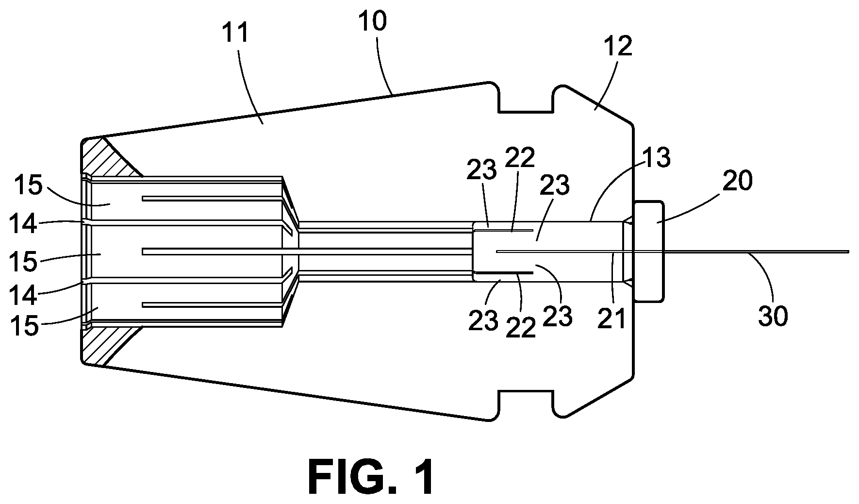
[0013] FIG. 1 is a sectional view of a chuck according to the invention;
[0014] FIG. 2 is an exploded view of FIG. 1; and
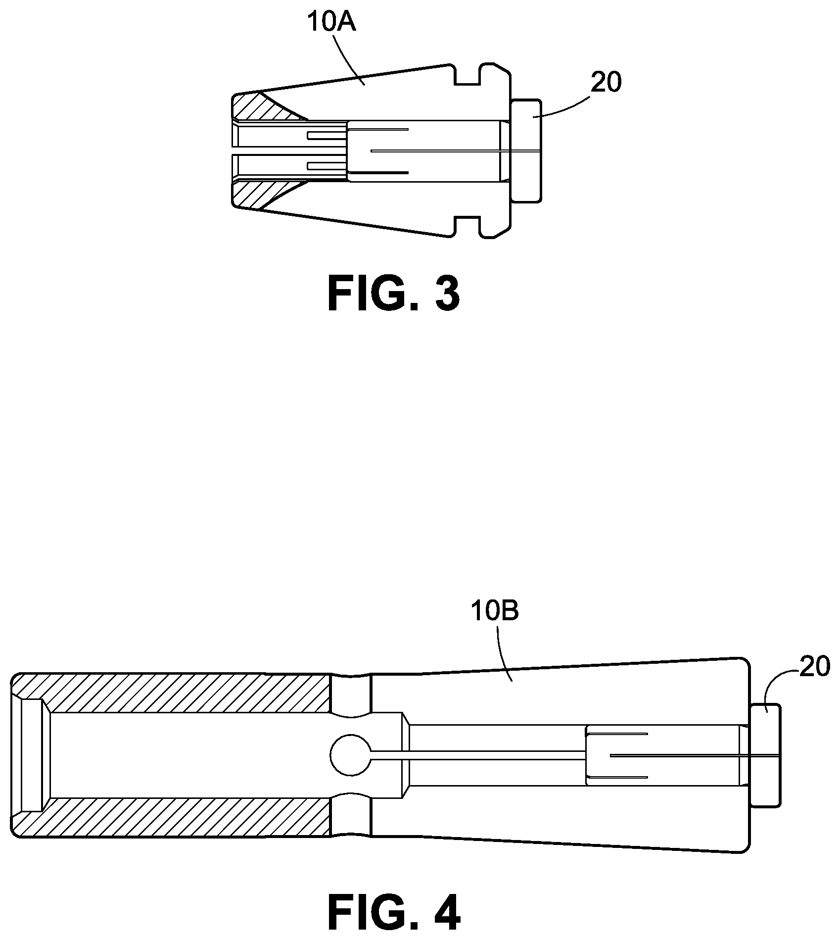
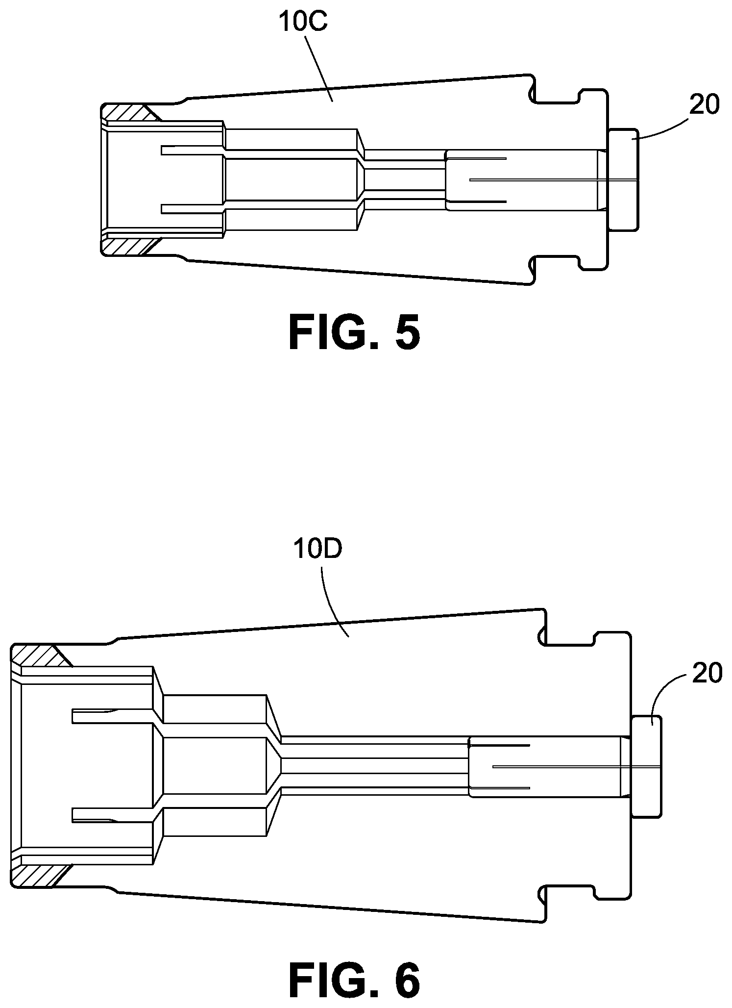
[0015] FIGS. 3, 4, 5 and 6 are sectional views each showing the collet secured to one of four different mounting parts.
DETAILED DESCRIPTION OF THE INVENTION
[0016] Referring to FIGS. 1 to 3, a chuck in accordance with the invention comprises a mounting part 10 and a collet 20 as discussed in detail below.
[0017] The mounting part 10 includes a conic connection member 11 and a hollow support member 12 integrally formed with the connection member 11. An end of the connection member 11 is mounted to quill of a mill, a drill, a lathe, or the like (all not shown). The support member 12 has an axial, stepped-diameter channel 13 with a substantial portion of the collet 20 disposed therein.
[0018] The collet 20 include an axial slit 21 for receipt a portion of a drill bit 30, a plurality of longitudinal first gaps 22 on a surface, each first gap 22 having an open end, and a plurality of first latches 23 each formed between two adjacent first gaps 22.
[0019] The mounting part 10 further comprises a plurality of longitudinal second gaps 14, each second gap 24 having an open end, and a plurality of second latches 25 each formed between two adjacent second gaps 24.
[0020] A fastener (not shown) may be secured to the mounting part 10. For example, the fastener is implemented as a nut which exerts a compressing force on the first latches 15. And in turn, the first latches 15 are flexibly deformed to exert a force to clamp the collet 20. Further, the force exerted on the collet 20 is transmitted to the first latches 23. And in turn, the first latches 23 are flexibly deformed to exert a force to clamp the drill bit 30 in the slit 21.
[0021] Referring to FIGS. 3 to 6, the collet 20 can be fastened by one of a plurality of different mounting parts such as a mounting part 10A of FIG. 3, a mounting part 10B of FIG. 4, a mounting part 10C of FIG. 5 and a mounting part 10D of FIG. 6. And in turn, each of the mounting parts 10A, 10B, 10C and 10D is mounted to a quill of a mill, a drill, a lathe, or the like (all not shown).
[0022] It is envisaged by the invention that the chuck has a collet fastened by a mounting part which is mounted to a quill of a mill, a drill, a lathe, or the like. Further, the collet has advantages of being compact, capable of fastening the drill bit, having improved precision, being convenient in operation, and capable of greatly decreasing the manufacturing cost.
[0023] Many changes and modifications in the above described embodiment of the invention can, of course, be carried out without departing from the scope thereof. Accordingly, to promote the progress in science and the useful arts, the invention is disclosed and is intended to be limited only by the scope of the appended claims.
* * * * *
D00000
D00001
D00002
D00003
D00004
XML
uspto.report is an independent third-party trademark research tool that is not affiliated, endorsed, or sponsored by the United States Patent and Trademark Office (USPTO) or any other governmental organization. The information provided by uspto.report is based on publicly available data at the time of writing and is intended for informational purposes only.
While we strive to provide accurate and up-to-date information, we do not guarantee the accuracy, completeness, reliability, or suitability of the information displayed on this site. The use of this site is at your own risk. Any reliance you place on such information is therefore strictly at your own risk.
All official trademark data, including owner information, should be verified by visiting the official USPTO website at www.uspto.gov. This site is not intended to replace professional legal advice and should not be used as a substitute for consulting with a legal professional who is knowledgeable about trademark law.