Ammunition Magazine
Bush; Michael D.
U.S. patent application number 16/113118 was filed with the patent office on 2020-02-27 for ammunition magazine. This patent application is currently assigned to Vudoo Labs, Inc. dba Vudoo Gun Works, LLC. The applicant listed for this patent is Vudoo Labs, Inc. dba Vudoo Gun Works, LLC. Invention is credited to Michael D. Bush.
| Application Number | 20200064091 16/113118 |
| Document ID | / |
| Family ID | 69583844 |
| Filed Date | 2020-02-27 |


| United States Patent Application | 20200064091 |
| Kind Code | A1 |
| Bush; Michael D. | February 27, 2020 |
AMMUNITION MAGAZINE
Abstract
Ammunition magazines have a lower magazine body having a body profile adapted to be closely received in the magazine well, the lower magazine body having an elongated upper surface, a magazine tower protruding above the upper surface and having a free upper end defining an ammunition exit aperture, an ammunition receptacle passage registered with the magazine tower, the magazine tower having a limited tower profile smaller than the body profile and adapted to be closely received in the magazine aperture, the magazine body having a front surface defining a vertical plane of reference, and the magazine tower having a front surface angled rearwardly with respect to the vertical plane of reference. The magazine tower may be tapered. The magazine tower may have a greater length adjacent to the body elongated upper surface than at the free upper end.
| Inventors: | Bush; Michael D.; (Somers, CT) | ||||||||||
| Applicant: |
|
||||||||||
|---|---|---|---|---|---|---|---|---|---|---|---|
| Assignee: | Vudoo Labs, Inc. dba Vudoo Gun
Works, LLC St. George UT |
||||||||||
| Family ID: | 69583844 | ||||||||||
| Appl. No.: | 16/113118 | ||||||||||
| Filed: | August 27, 2018 |
| Current U.S. Class: | 1/1 |
| Current CPC Class: | F41A 33/00 20130101; F41A 9/70 20130101; F41A 3/66 20130101; F41A 21/10 20130101; F41A 9/71 20130101; F41A 9/67 20130101 |
| International Class: | F41A 9/67 20060101 F41A009/67 |
Claims
1. An ammunition magazine for a firearm having a magazine well, a magazine aperture above the well and in communication with the well, and a magazine latch in communication with the well, the magazine comprising: a lower magazine body having a body profile adapted to be closely received in the magazine well, and having an upper end and an opposed lower end; the lower magazine body having an elongated upper surface facing away from the opposed lower end; a magazine tower protruding above the elongated upper surface and having a free upper end defining an ammunition exit aperture; an ammunition receptacle passage registered with the magazine tower; the magazine tower having a limited tower profile smaller than the body profile and adapted to be closely received in the magazine aperture; the magazine body having a front surface defining a vertical plane of reference; and the magazine tower having a front surface angled rearwardly with respect to the vertical plane of reference.
2. The ammunition magazine of claim 1 wherein the magazine tower is tapered.
3. The ammunition magazine of claim 1 wherein the magazine tower has a greater length adjacent to the lower magazine body elongated upper surface than at the free upper end.
4. The ammunition magazine of claim 1 wherein the front surface of the magazine tower is aft of the front surface of the lower magazine body.
5. The ammunition magazine of claim 4 including a forward portion of the lower magazine body elongated upper surface being forward of the magazine tower.
6. The ammunition magazine of claim 5 wherein the ammunition magazine toward the front surface of the magazine tower and the forward portion of the lower magazine body elongated upper surface defines an interior angle adapted to receive a portion of the firearm defining a forward portion of the magazine aperture.
7. The ammunition magazine of claim 1 wherein the lower magazine body has a rear surface including a catch adapted for engagement by a movable latch on the firearm.
8. The ammunition magazine of claim 1 wherein the catch has a downward facing catch surface.
9. (canceled)
10. An ammunition magazine for a firearm having a magazine well, a magazine aperture above the well and in communication with the well, and a magazine latch in communication with the well, the magazine comprising: a lower magazine body having a body profile adapted to be closely received in the magazine well, and having an upper end and an opposed lower end; the lower magazine body having an elongated upper surface facing away from the opposed lower end; a magazine tower protruding above the elongated upper surface and having a free upper end defining an ammunition exit aperture; an ammunition receptacle passage registered with the magazine tower; the magazine tower having a limited tower profile smaller than the body profile and adapted to be closely received in the magazine aperture; the magazine body having a rear surface defining a vertical plane of reference; and the magazine tower having a front surface angled rearwardly with respect to the vertical plane of reference.
11. The ammunition magazine of claim 10 wherein the magazine tower is tapered.
12. The ammunition magazine of claim 10 wherein the magazine tower has a greater length adjacent to the lower magazine body elongated upper surface than at the free upper end.
13. The ammunition magazine of claim 10 wherein the front surface of the magazine tower is aft of the front surface of the lower magazine body.
14. The ammunition magazine of claim 13 including a forward portion of the lower magazine body elongated upper surface being forward of the magazine tower.
15. The ammunition magazine of claim 14 wherein the ammunition magazine toward the front surface of the magazine tower and the forward portion of the lower magazine body elongated upper surface defines an interior angle adapted to receive a portion of the firearm defining a forward portion of the magazine aperture.
16. The ammunition magazine of claim 10 wherein the lower magazine body has a rear surface including a catch adapted for engagement by a movable latch on the firearm.
17. The ammunition magazine of claim 10 wherein the catch has a downward facing catch surface.
18. (canceled)
Description
FIELD OF THE INVENTION
[0001] The present invention relates to firearms, and more particularly to an ammunition magazine having an outer form shaped to be received in a full-length centerfire cartridge magazine well and stock that dispenses shorter 22LR caliber cartridges.
BACKGROUND OF THE INVENTION
[0002] A magazine is an ammunition storage and feeding device within, or attached to, a repeating firearm. The magazine functions by moving the cartridges stored in the magazine into a position where they may be chambered by the action of the firearm. Most magazines designed for use with a reciprocating bolt firearm utilize a set of feed lips which stops the vertical motion of the cartridges out of the magazine but allows one cartridge at a time to be pushed forward (stripped) out of the feed lips by the firearm's bolt into the chamber.
[0003] Some form of spring and follower combination is almost always used to feed cartridges to the lips, which can be located either in the magazine (most removable box magazines) or built into the firearm (fixed box magazines). A box (or "stick") magazine, the most popular type of magazine in modern rifles and handguns, stores cartridges in a straight or gently curved column, either one above the other or staggered zigzag fashion. As the firearm cycles, cartridges are moved to the top of the magazine by a follower driven by spring compression to either a single feed position or alternating feed positions. In most firearms, the magazine follower engages a slide-stop to hold the slide back and keep the firearm out of battery when the magazine is empty, and all rounds have been fired. Box magazines may be integral to the firearm or removable.
[0004] A detachable box magazine is a self-contained mechanism capable of being loaded or unloaded while detached from the host firearm. They are inserted into a magazine well in the firearm receiver usually below the action, but occasionally positioned to the side or on top. When the magazine is empty, it can be detached from the firearm and replaced by another full magazine while the firearm remains in an operable state. This significantly speeds the process of reloading, allowing the operator quick access to ammunition. This type of magazine may be straight or curved, the curve being necessary if the rifle uses rimmed ammunition or ammunition with a tapered case.
[0005] It is often desirable for shooters to be able to hunt small game or practice shooting with less powerful and/or less expensive ammunition. The relatively low cost and widespread availability makes the ability to fire 22LR caliber rimfire ammunition in more powerful, higher caliber centerfire firearms particularly attractive. The lower power 22LR caliber rimfire ammunition allows a shooter to become familiar with the feel of the firearm while shooting a round that has less recoil and is considerably cheaper than larger centerfire calibers. Moreover, the reduced power of the smaller 22LR caliber rimfire ammunition allows it to be shot at smaller range facilities.
[0006] Therefore, a need exists for a new and improved ammunition magazine that has an outer form shaped to be received in a full-length centerfire cartridge magazine well and stock that dispenses shorter 22LR caliber cartridges. In this regard, the various embodiments of the present invention substantially fulfill at least some of these needs. In this respect, the ammunition magazine according to the present invention substantially departs from the conventional concepts and designs of the prior art, and in doing so provides an apparatus primarily developed for the purpose of providing an ammunition magazine that has an outer form shaped to be received in a full-length cartridge magazine well and stock that dispenses shorter 22LR caliber cartridges.
SUMMARY OF THE INVENTION
[0007] The present invention provides an improved ammunition magazine, and overcomes the above-mentioned disadvantages and drawbacks of the prior art. As such, the general purpose of the present invention, which will be described subsequently in greater detail, is to provide an improved ammunition magazine that has all the advantages of the prior art mentioned above.
[0008] To attain this, the preferred embodiment of the present invention essentially comprises a lower magazine body having a body profile adapted to be closely received in the magazine well, the lower magazine body having an elongated upper surface, a magazine tower protruding above the upper surface and having a free upper end defining an ammunition exit aperture, an ammunition receptacle passage registered with the magazine tower, the magazine tower having a limited tower profile smaller than the body profile and adapted to be closely received in the magazine aperture, the magazine body having a front surface defining a vertical plane of reference, and the magazine tower having a front surface angled rearwardly with respect to the vertical plane of reference. The magazine tower may be tapered. The magazine tower may have a greater length adjacent to the body elongated upper surface than at the free upper end. There are, of course, additional features of the invention that will be described hereinafter and which will form the subject matter of the claims attached.
[0009] There has thus been outlined, rather broadly, the more important features of the invention in order that the detailed description thereof that follows may be better understood and in order that the present contribution to the art may be better appreciated.
BRIEF DESCRIPTION OF THE DRAWINGS
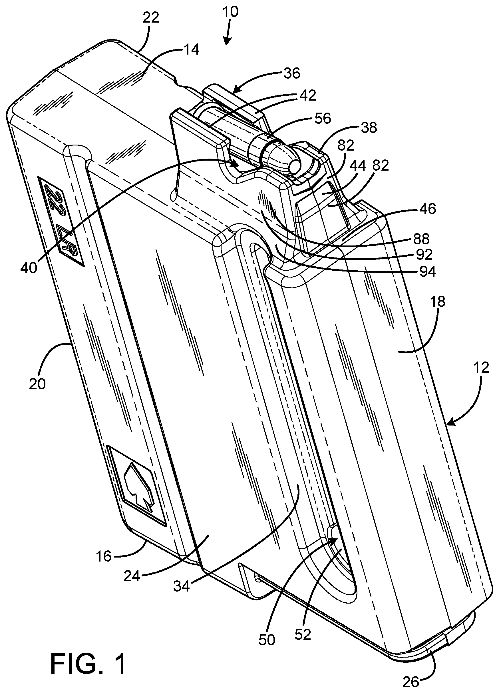
[0010] FIG. 1 is a front isometric view of the current embodiment of the ammunition magazine constructed in accordance with the principles of the present invention.
[0011] FIG. 2 is a rear isometric view of the ammunition magazine of FIG. 1 with a firearm suitable for use with the ammunition magazine of the present invention.
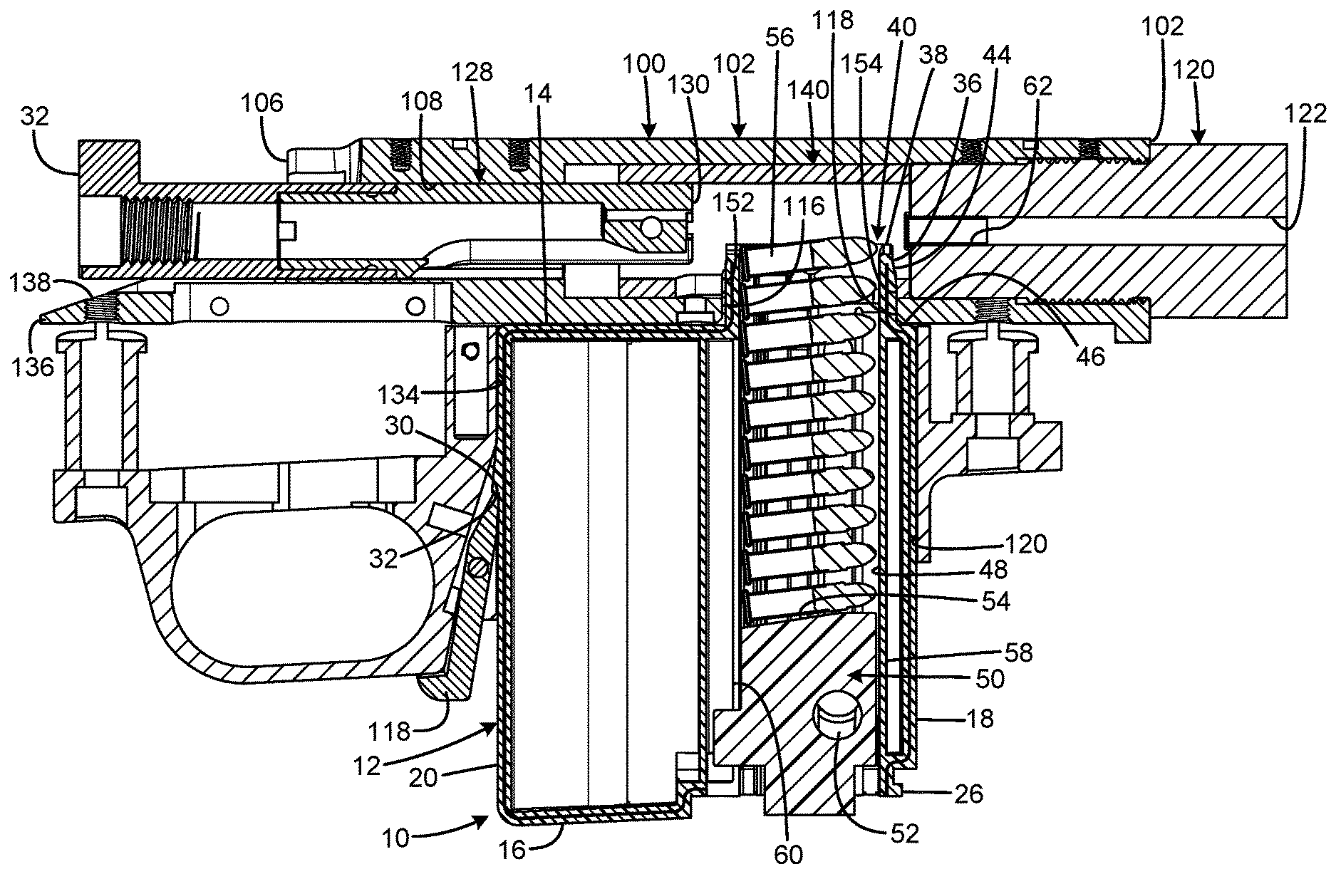
[0012] FIG. 3 is a side sectional view of the ammunition magazine of FIG. 1 installed in the firearm of FIG. 2.
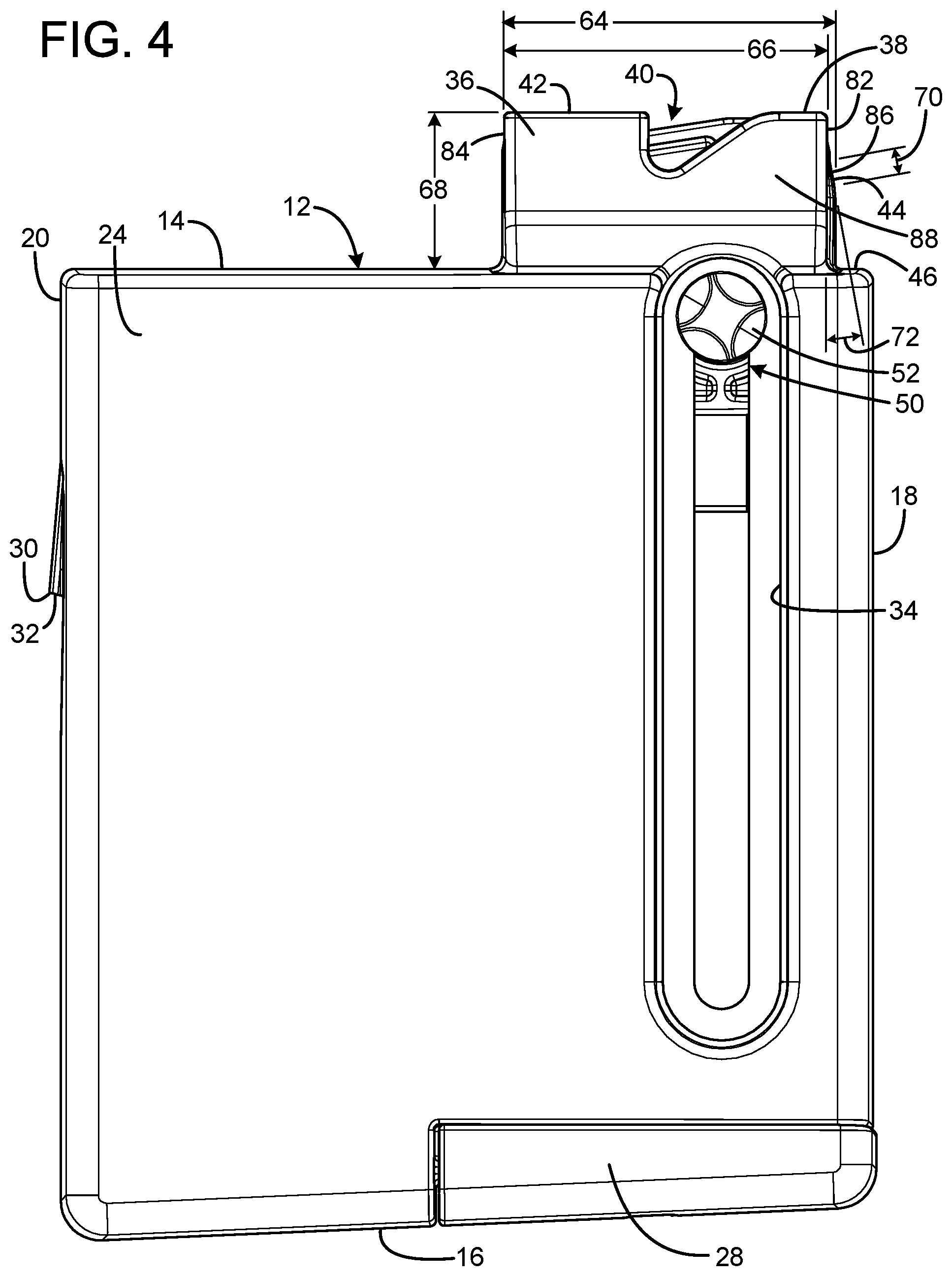
[0013] FIG. 4 is a left side view of the ammunition magazine of FIG. 1.
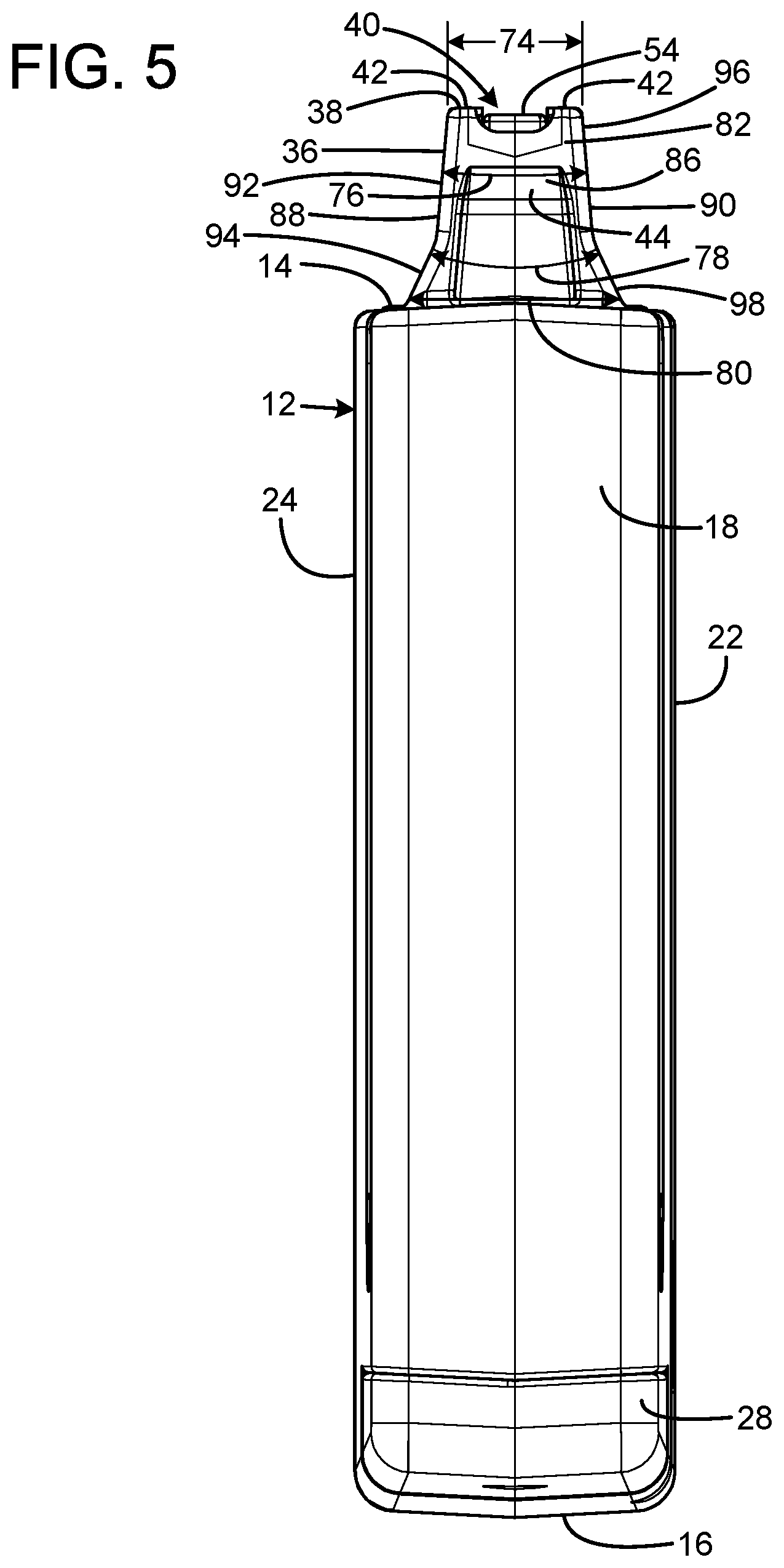
[0014] FIG. 5 is a front view of the ammunition magazine of FIG. 1.
[0015] The same reference numerals refer to the same parts throughout the various figures.
DESCRIPTION OF THE CURRENT EMBODIMENT
[0016] A current embodiment of the ammunition magazine of the present invention is shown and generally designated by the reference numeral 10.
[0017] FIGS. 1-3 illustrate the improved ammunition magazine 10 of the present invention. More particularly, the ammunition magazine has a lower magazine body 12 having an elongated upper surface 14, a bottom surface 16 a body front surface 18, a body rear surface 20, a left side 22, and a right side 24. A forward portion of the bottom surface includes a base plate retainer 26 that slidably receives a base plate 28. The body rear surface includes a catch 30 having a downward facing catch surface 32. The right side of the lower magazine body defines a side slot 34.
[0018] A magazine tower 36 protrudes above the elongated upper surface 14 of the lower magazine body 12. The magazine tower has a free upper end 38 that defines an ammunition exit aperture 40 and includes feed lips 42. The magazine tower has a tower front surface 44 that is angled rearwardly with respect to a vertical plane of reference defined by the body front surface 18. Thus, the magazine tower is tapered and has a greater length adjacent to the elongated upper surface 14 of the lower magazine body 12 than at the free upper end of the magazine tower. The tower front surface is aft of the body front surface such that a forward portion 46 of the elongated upper surface of the lower magazine body is forward of the magazine tower.
[0019] An ammunition receptacle passage 48 within a forward portion of the lower magazine body 12 is registered with the magazine tower 36. The ammunition receptacle receives a follower 50 that is biased upward within the ammunition receptacle passage by a coil spring (not shown). The follower includes a thumb button 52 and a top 54. The thumb button protrudes through the side slot 34, which enables the thumb button to be pulled downward by a user's thumb to facilitate the loading of cartridges 56 through the ammunition exit aperture 40 into the ammunition receptacle passage 48. When the user releases the thumb button, the coil spring urges the follower upwards to compress the cartridges between the top of the follower and the feed lips 42. Fore and aft movement of the cartridges within the lower magazine body is constrained by a front wall 58 and a rear wall 60 that define the ammunition receptacle passage.
[0020] A firearm 100 suitable for use with the ammunition magazine 10 of the present invention includes an elongated cylindrical receiver body 102 having an open front 104, open rear 106, a hollow interior 108, right side 110, and bottom 112. The right side of the receiver body defines an ejection port 114, and the bottom of the receiver body defines a magazine aperture 116 having a forward portion 118. Both the ejection port and the magazine aperture communicate with the hollow interior of the receiver body. The ejection port enables spent cartridge casings 62 to be expelled from the receiver body.
[0021] A magazine well 120 extends downwardly from the bottom 112 of the receiver body 102 in communication with the magazine aperture 116. A movable magazine latch 118 is attached to the firearm 100 in communication with the magazine well. A barrel 120 defining a central barrel bore 122 has a rear 124 threadedly received by a threaded portion 136 of the open front 104 of the receiver body. The rear of the barrel bore defines a chamber 126 that is sized to closely receive a cartridge 56. A bolt 128 having a front 130 and rear 132 has its front slidably received within the open rear 106 of the receiver body. A tang 136 that defines a bolt handle notch 138 protrudes rearwardly from the bottom rear of the receiver body.
[0022] An insert 140 is an elongate cylindrical sleeve received within the hollow interior 108 of the receiver body 102. The insert has a front 142, rear 144, right side 146, left side (not visible), and bottom 148. The front and rear of the insert are open, defining a hollow interior 150. The bottom of the insert defines a magazine aperture 152 having a forward portion 154 that communicates with the interior 150. The right side of the insert defines an ejection port 156 that communicates with the interior 150 and enables spent cartridge casings to be expelled from the insert. It should be appreciated that the magazine aperture 152 and ejection port 156 of the insert are sized and positioned such that they are axially registered with the magazine aperture 116 and ejection port 114 of the receiver body when the insert is installed within the hollow interior of the receiver body.
[0023] When the ammunition magazine 10 is installed in the magazine well 120, an interior angle defined by tower front surface 44 and the forward portion 46 of the elongated upper surface 14 of the lower magazine body 12 receives the forward portion 118 of the magazine aperture 116 defined by the bottom 112 of the receiver body 102. The tapered tower front surface 44 of the magazine tower 36 provides a secure position fit as the magazine tower is inserted into the magazine apertures 116, 152 by shifting the ammunition magazine rearward against the pressure of the movable magazine latch to create compression against the rear wall 134 of the magazine well. The magazine latch removably secures the ammunition magazine within the magazine well once the ammunition magazine is inserted far enough for the magazine latch to engage the downward facing catch surface 32 on the catch 30.
[0024] The firearm 100 suitable for use with the ammunition magazine 10 is a 0.22LR rimfire bolt action rifle in the current embodiment. The ammunition magazine is a turn-pull design: the user performs an upward lifting movement of the bolt handle (not shown) to disengage the bolt handle from the bolt handle notch 138 and to turn and unlock the bolt 128 from the breech and cock the firing pin, followed by pulling the bolt handle rearward to open the breech, extract the spent cartridge casing 62 and eject the spent cartridge casing through the ejection ports 114, 156. The user reverses the process to chamber the next cartridge 56 by stripping a cartridge from the magazine tower 36 of the ammunition magazine 10 protruding through the magazine apertures 116, 152 and relocking the breech via a lowering movement of the bolt handle into the bolt handle notch to turn and lock the bolt.
[0025] It should be appreciated that the lower magazine body 12 of the ammunition magazine 10 has a body profile adapted to be closely received in an Accuracy International Chassis Systems (AICS)-style full length centerfire cartridge magazine well, thus making the ammunition magazine 10 suitable for use with any firearm having either an AICS-style magazine well or AICS-compatible detachable bottom metal (DBM) and a rimfire action of the proper diameter and length. The ammunition magazine 10 is also compatible with magazine pouches and other accessories for AICS-style full length centerfire cartridge magazines. The magazine tower 36, ammunition receptacle passage 48, and follower are all sized for the shorter 22LR caliber cartridges to ensure proper feeding from what would otherwise be an oversized magazine. Furthermore, although the magazine tower and ammunition receptacle passage have been integral to the ammunition magazine 10, it should be appreciated that the ammunition magazine 10 could also be manufactured by first forming the magazine tower and the front and rear walls 58, 60 as a standalone magazine and then inserting the standalone magazine into an AICS-style housing.
[0026] In the current embodiment, the ammunition magazine 10 includes seven individual components. Six are injection molded, and the seventh is the coil spring. The injection molded components are right and left housing halves that are ultrasonically welded to become a one-piece lower magazine body, a follower, a thumb button attached to the follower, a base plate, and a base plate retainer. The ammunition magazine 10 houses and properly aligns up to ten 22LR caliber cartridges in a vertical column. The cartridges are held statically at the proper angle and under pressure provided by the coil spring and follower. As a single cartridge is stripped from the ammunition magazine 10 during the forward movement of the bolt, spring pressure pushes the follower and the column of cartridges up, which positions the next cartridge to be fed into the chamber. The feed lips limit the upward movement of the cartridges, but allow the upward and forward stripping movement of the uppermost cartridge to occur so the uppermost cartridge can be fed into the chamber by the bolt. The cartridges are constrained by the forward, aft and side walls that define the ammunition receptacle passage, which are internal features of the left and right magazine housing halves. These walls do not allow any other movement other than downward motion of the column of cartridges for loading the magazine and upward movement of the column of cartridges as they are stripped singularly from the magazine during chambering. The slight space forward of the ammunition receptacle passage, and the larger space behind the ammunition receptacle passage, are necessary to enable the lower magazine body to meet the physical requirements to emulate the AICS envelope.
[0027] Referring now to FIGS. 4-5, in the current embodiment the magazine tower 36 has the following specifications. The length 64 of the magazine tower, including the tower front surface 44, is 1.25 inch. The front and rear walls 82, 84 of the magazine tower are tapered at an angle 66 of 0.53.degree.. The height 68 of the magazine tower is 0.59 inch. The tower front surface has an upper portion having a height of 0.10 inches that is tapered at an angle 72 of 10.40.degree. relative to vertical. The width 74 of the magazine tower at the free upper end 38 is 0.41 inch. The right and left walls 88, 90 of the magazine tower each have an upper portion 92, 96 and lower portion 94, 98. The upper portions of the right and left walls are tapered at an angle 76 of 10.degree.. The lower portions of the right and left walls are tapered at an angle 78 of 50.degree.. The width 80 of the magazine tower where the right and left walls contact the elongated upper surface 14 of the lower magazine body 12 is 0.64 inch.
[0028] In the context of the specification, the terms "rear" and "rearward," and "front" and "forward" have the following definitions: "rear" or "rearward" means in the direction away from the muzzle of the firearm while "front" or "forward" means it is in the direction towards the muzzle of the firearm.
[0029] While a current embodiment of an ammunition magazine has been described in detail, it should be apparent that modifications and variations thereto are possible, all of which fall within the true spirit and scope of the invention. With respect to the above description then, it is to be realized that the optimum dimensional relationships for the parts of the invention, to include variations in size, materials, shape, form, function and manner of operation, assembly and use, are deemed readily apparent and obvious to one skilled in the art, and all equivalent relationships to those illustrated in the drawings and described in the specification are intended to be encompassed by the present invention. Therefore, the foregoing is considered as illustrative only of the principles of the invention. Further, since numerous modifications and changes will readily occur to those skilled in the art, it is not desired to limit the invention to the exact construction and operation shown and described, and accordingly, all suitable modifications and equivalents may be resorted to, falling within the scope of the invention.
* * * * *
D00000
D00001
D00002
D00003
D00004
D00005
XML
uspto.report is an independent third-party trademark research tool that is not affiliated, endorsed, or sponsored by the United States Patent and Trademark Office (USPTO) or any other governmental organization. The information provided by uspto.report is based on publicly available data at the time of writing and is intended for informational purposes only.
While we strive to provide accurate and up-to-date information, we do not guarantee the accuracy, completeness, reliability, or suitability of the information displayed on this site. The use of this site is at your own risk. Any reliance you place on such information is therefore strictly at your own risk.
All official trademark data, including owner information, should be verified by visiting the official USPTO website at www.uspto.gov. This site is not intended to replace professional legal advice and should not be used as a substitute for consulting with a legal professional who is knowledgeable about trademark law.