High Pressure Die Cast (hpdc) Aluminum Alloy Heat Treatment For Improved Rivetability Via Modification Of As-cast Structure
Zindel; Jacob Wesley ; et al.
U.S. patent application number 16/033766 was filed with the patent office on 2020-01-16 for high pressure die cast (hpdc) aluminum alloy heat treatment for improved rivetability via modification of as-cast structure. This patent application is currently assigned to Ford Motor Company. The applicant listed for this patent is Ford Motor Company. Invention is credited to Daniel Scott Freiberg, Amanda Kay Freis, Garret Huff, Jacob Wesley Zindel.
| Application Number | 20200017945 16/033766 |
| Document ID | / |
| Family ID | 69138702 |
| Filed Date | 2020-01-16 |
View All Diagrams
| United States Patent Application | 20200017945 |
| Kind Code | A1 |
| Zindel; Jacob Wesley ; et al. | January 16, 2020 |
HIGH PRESSURE DIE CAST (HPDC) ALUMINUM ALLOY HEAT TREATMENT FOR IMPROVED RIVETABILITY VIA MODIFICATION OF AS-CAST STRUCTURE
Abstract
A method of treating a high pressure die cast (HPDC) material to improve rivetability is provided. The method includes exposing the HPDC material to a temperature between 300.degree. C. and 450.degree. C. for a time period between 10 minutes and 5 hours in a heat treatment step. In this method, the heat treatment results in eutectic silicon spheroidization of the HPDC material such that the HPDC material does not crack after rivet installation. The method further includes the step of exposing the HPDC material to a subsequent heat treatment step at about 180.degree. C. for about 30 minutes after quenching. Moreover, the quenching may be a forced air quench for a period of 6.degree. C./s.
| Inventors: | Zindel; Jacob Wesley; (Ann Arbor, MI) ; Freis; Amanda Kay; (Ann Arbor, MI) ; Huff; Garret; (Ann Arbor, MI) ; Freiberg; Daniel Scott; (Dearborn, MI) | ||||||||||
| Applicant: |
|
||||||||||
|---|---|---|---|---|---|---|---|---|---|---|---|
| Assignee: | Ford Motor Company Dearborn MI |
||||||||||
| Family ID: | 69138702 | ||||||||||
| Appl. No.: | 16/033766 | ||||||||||
| Filed: | July 12, 2018 |
| Current U.S. Class: | 1/1 |
| Current CPC Class: | C22F 1/002 20130101; C22F 1/043 20130101; C22C 21/02 20130101 |
| International Class: | C22F 1/043 20060101 C22F001/043; C22F 1/00 20060101 C22F001/00; C22C 21/02 20060101 C22C021/02 |
Claims
1. A method of treating a high pressure die cast (HPDC) material to improve rivetability, the method comprising: exposing the HPDC material to a temperature between 300.degree. C. and 450.degree. C. for a time period between 10 minutes and 5 hours in a heat treatment step; wherein the heat treatment result in eutectic silicon spheroidization of the HPDC material such that the HPDC material does not crack due to rivet installation, wherein the composition of the HPDC material comprises: TABLE-US-00004 Minimum Maximum Element wt. % wt. % Copper (Cu) 0.00 0.03 Iron* (Fe) 0.00 0.20 Magnesium (Mg) 0.10 0.60 Manganese* (Mn) 0.45 0.80 Phosphorus (P) 0.00 0.001 Silicon (Si) 7.00 11.50 Strontium (Sr) 0.00 0.03 Titanium (Ti) 0.00 0.15 Zinc (Zn) 0.00 0.07 Individual Impurities 0.00 0.05 Total Impurities 0.00 0.15 Aluminum (Al) Balance wherein the wt. % Fe + the wt. % Mn < 0.95.
2. The method according to claim 1 further comprising the step of exposing the HPDC material to a subsequent heat treatment step at about 180.degree. C. for about 30 minutes.
3. The method according to claim 2, wherein the subsequent heat treatment step results in a yield strength of at least about 80 MPa for an aluminum alloy.
4. The method according to claim 1, wherein the eutectic silicon spheroidization comprises fewer than an average of about 3.50.times.10{circumflex over ( )}5 silicon particles per mm{circumflex over ( )}2 in any of the Al--Si eutectic microstructural constituents of the HPDC material.
5. The method according to claim 1, wherein the temperature of the heat treatment step is 450.degree. C. and the time period is between 10-30 minutes to result in full spheroidization of silicon eutectic, wherein there are fewer than about 1.50.times.10{circumflex over ( )}5 silicon particles per mm{circumflex over ( )}2 in any of the Al--Si eutectic microstructural constituents of an HPDC material.
6. The method according to claim 1, wherein the temperature of the heat treatment step is between 300.degree. C. to 450.degree. C. and the time period is between 30 minutes to 2 hours to result in intermediate spheroidization of silicon eutectic, wherein there are between about 3.50.times.10{circumflex over ( )}5 and about 1.50.times.10{circumflex over ( )}5 silicon particles per mm{circumflex over ( )}2 in any of the Al--Si eutectic microstructural constituents of an HPDC material.
7. The method according to claim 1, wherein the temperature of the heat treatment step is 300.degree. C. and the time period is between 2 to 5 hours to result in partial spheroidization of silicon eutectic, wherein there are fewer than about 3.50.times.10{circumflex over ( )}5 silicon particles per mm{circumflex over ( )}2 in an HPDC material.
8. The method according to claim 1, wherein the HPDC material is an aluminum alloy.
9. The method according to claim 1 further comprising a step of quenching the HPDC material after the heat treatment.
10. The method according to claim 1, wherein the heat treatment are localized over predetermined portions of the HPDC material.
11. The method according to claim 1, wherein the quenching is a forced air quench for a period of 6.degree. C./s.
12. A part formed according to the method of claim 1.
13. A method of treating a high pressure die cast (HPDC) material to improve rivetability, the method comprising: exposing the HPDC material to a temperature between 300.degree. C. and 450.degree. C. for a time period between 10 minutes and 2 hours in an initial heat treatment step; and exposing the HPDC material to a subsequent heat treatment step at about 180.degree. C. for about 30 minutes after quenching, wherein the heat treatment results in eutectic silicon spheroidization of the HPDC material such that the HPDC material does not crack after rivet installation and the subsequent heat treatment step increases yield strength of the HPDC material.
14. The method according to claim 13, wherein the subsequent heat treatment step results in a yield strength of at least about 80 MPa for an aluminum alloy.
15. The method according to claim 13, wherein the eutectic silicon spheroidization comprises fewer than an average of about 3.50.times.10{circumflex over ( )}5 silicon particles per mm{circumflex over ( )}2 in any of the Al--Si eutectic microstructural constituents of the HPDC material.
16. The method according to claim 13, wherein the heat treatments are localized over predetermined portions of the HPDC material.
17. A method of treating an aluminum high pressure die cast (HPDC) material to improve rivetability, the method comprising: exposing the aluminum HPDC material to a temperature between 300.degree. C. and 450.degree. C. for a time period between 10 minutes and 2 hours in an initial heat treatment step; quenching the aluminum HPDC material; and exposing the aluminum HPDC material to a subsequent heat treatment step at about 180.degree. C. for about 30 minutes after quenching, wherein the heat treatment results in eutectic silicon spheroidization of the aluminum HPDC material such that the aluminum HPDC material does not crack after rivet installation and the subsequent heat treatment step increases yield strength of the aluminum HPDC material to at least 80 MPa.
18. The method according to claim 17, wherein the eutectic silicon spheroidization comprises fewer than an average of about 3.50.times.10{circumflex over ( )}5 silicon particles per mm{circumflex over ( )}2 in any of the Al--Si eutectic microstructural constituents of the HPDC material.
19. The method according to claim 17, wherein the heat treatments and the quenching are localized over predetermined portions of the HPDC material.
20. The method according to claim 17, wherein the quenching is a forced air quench for a period of 6.degree. C./s.
Description
FIELD
[0001] The present disclosure relates to the joining of high pressure die cast (HPDC) materials, including various aluminum alloys, with highly localized forming operations such as self-piercing riveting (SPR).
BACKGROUND
[0002] The statements in this section merely provide background information related to the present disclosure and may not constitute prior art.
[0003] For aluminum alloys, a T5-temper is an artificial age-hardening (strengthening) treatment that is applied to an as-cast (F-temper) Aluminum alloy. The T5 treatment often results in sufficient yield strength (YS) and elongation (% EL or EL) values without having to fully solution heat treat the aluminum alloy. The T5-temper is an advantageous heat treatment for High Pressure Die Cast (HPDC) aluminum alloys, especially Al--Si--Mg--Mn alloys in vehicle body structural applications.
[0004] Vehicle parts are often joined together to form an assembly, including HPDC parts to other HPDC or non-HPDC parts, which may be aluminum. A relatively inexpensive and reliable method of joining HPDC parts to other parts is self-piercing riveting (SPR). SPR is a mechanical fastening process for point joining sheet material, typically steels and aluminum alloys. The SPR process demands a reasonable amount of through-thickness fracture toughness to produce a robust joint. Normally, the reasonable amount of through-thickness fracture toughness is enabled by heat-treating the casting prior to riveting.
[0005] Unfortunately, when HPDC materials are subjected to a highly localized forming operation such as SPR, the HPDC material is susceptible to cracking. This cracking renders HPDC materials, generally, unfit for SPR processes, which significantly plastically deforms the substrates/parts being joined.
[0006] A fully solution treated and overaged HPDC aluminum alloy (e.g. T7-temper) does not readily form cracks during localized forming operations. Thus, the T7-temper has become the default temper for delivering material rivetability because the T7-temper has adequate through-thickness toughness. The component also satisfies designer requirements, offering high elongation with sufficient strength.
[0007] Unfortunately, the T7-heat treatment usually consists of a solution step followed by an air-blast quench then artificial aging. In addition to the cost of the heat treatment, additional costs are associated with increased dimensional distortion and blister scrap.
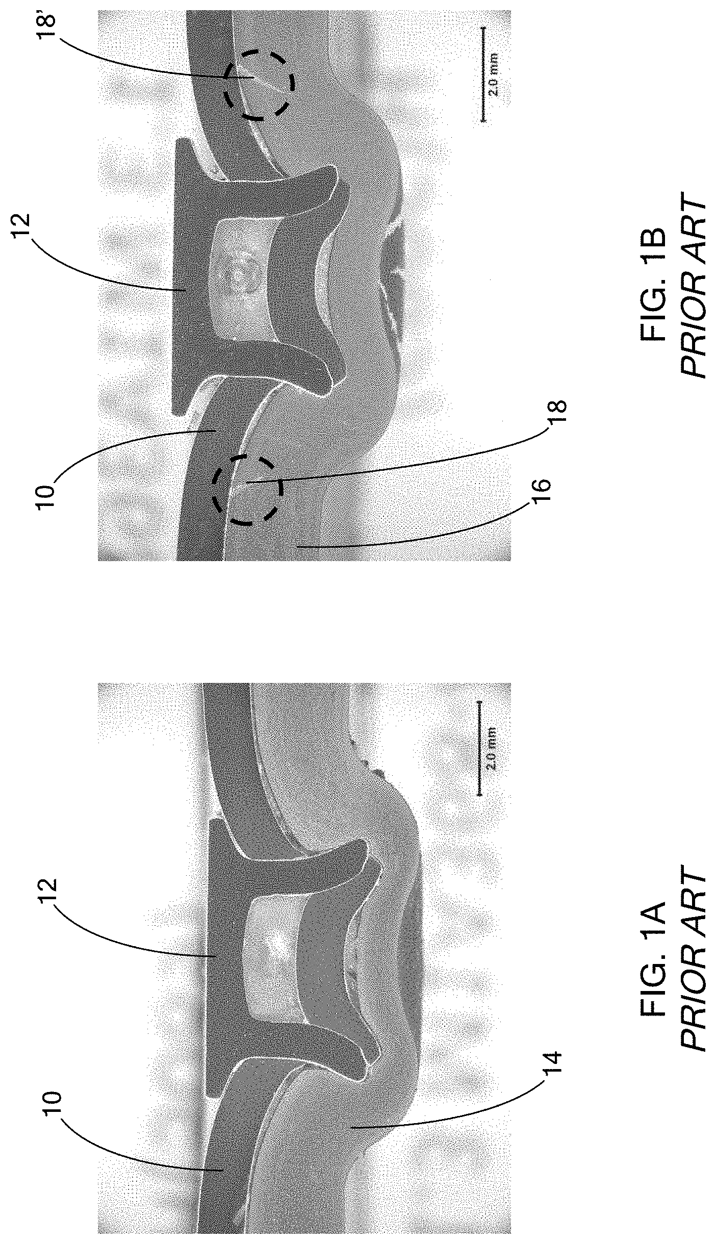
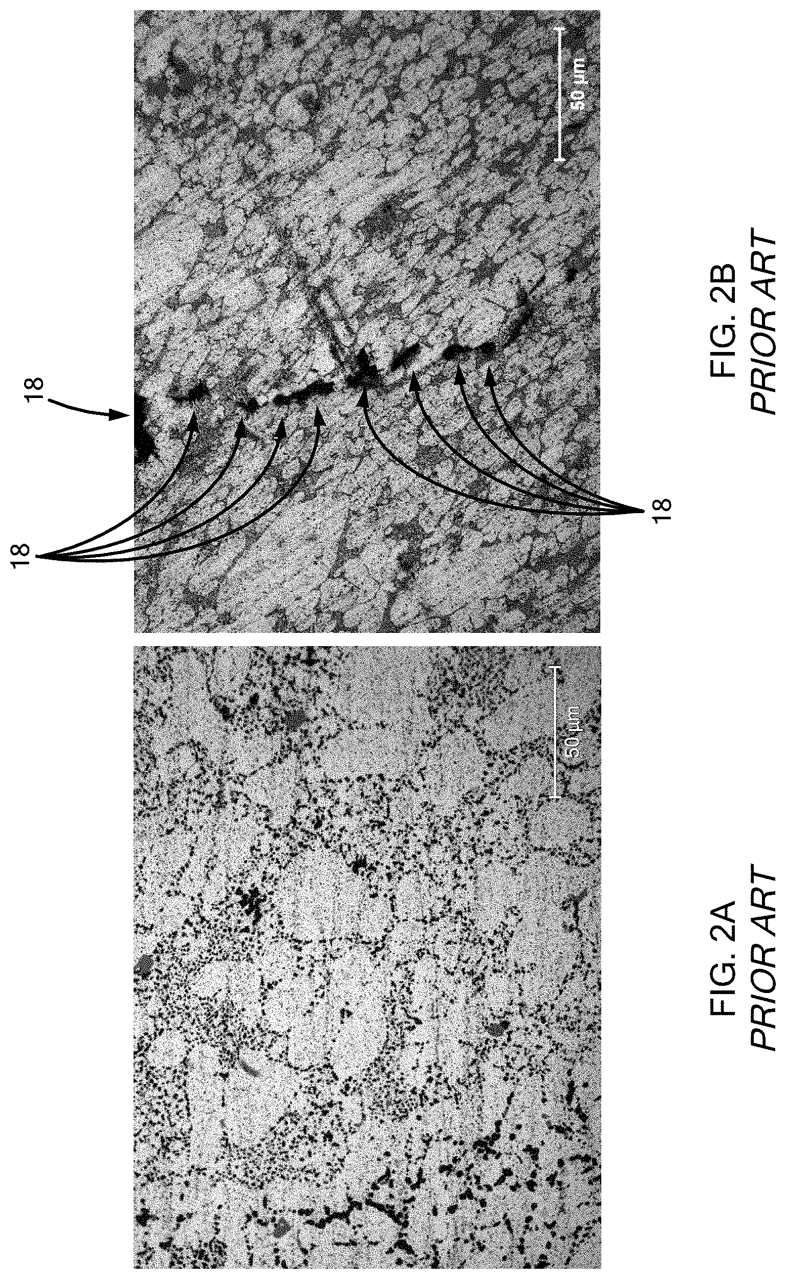
[0008] Now referring to FIGS. 1A-1B AND 2A-2B, a steel part 10 is shown that is joined by a self-piercing rivet 12 to an overaged HPDC-T7 aluminum alloy part 14 in FIGS. 1A and 2A, while a steel part 10 is joined by a self-piercing rivet 12 to an artificially aged HPDC-T5 aluminum alloy part 16 in FIGS. 1B and 2B. As shown, the T7-heat treated aluminum alloy part 14 exhibits no visible cracks, while the T5-heat treated aluminum alloy part 16 exhibits at least two visible cracks 18 and 18'.
[0009] To further complicate HPDC aluminum alloy processing, HPDC aluminum alloys may be used both in the "as-cast" and T4-temper conditions where the T4-temper is defined as material that has been solution treated and quenched after fabrication. It is often an unstable condition as natural aging (e.g. room temperature aging) may occur resulting in an increase in yield stress but a decrease in ductility. Additionally, "as-cast" HPDC aluminum alloys age during storage, thus altering (degrading) their rivetability.
[0010] The present disclosure addresses the issues of cracking when joining HPDC materials, such as aluminum alloys, particularly using SPR processes, among other issues related to joining HPDC materials.
SUMMARY
[0011] In one form of the present disclosure, a method of treating a high pressure die cast (HPDC) material to improve rivetability is provided. The method comprises exposing the HPDC material to a temperature between 300.degree. C. and 450.degree. C. for a time period between 10 minutes and 5 hours in a heat treatment step and quenching the HPDC material. In this method of the present disclosure, the heat treatment results in eutectic silicon spheroidization of the HPDC material such that the HPDC material does not crack after rivet installation, and more specifically self-piercing rivet installation in one form. In order to inhibit cracking, in one form, the eutectic silicon spheroidization comprises fewer than a minimum of about 3.50.times.10{circumflex over ( )}5 silicon particles per mm{circumflex over ( )}2 in any of the Al--Si eutectic microstructural constituents of the HPDC material. The primary aluminum phase, which is a dendritic structure, has no Si particles and therefore cannot be in the field of view for this measurement as it would bias the particle density values.
[0012] In a variation of the method of the present disclosure, the HPDC material is exposed to a subsequent heat treatment step, e.g. a paint bake step, at about 180.degree. C. for about 30 minutes after quenching. In this variation, the subsequent heat treatment step results in a yield strength of at least about 80 MPa for an aluminum alloy.
[0013] In another variation of the method of the present disclosure, the temperature of the heat treatment step is 450.degree. C. and the time period is between 10-30 minutes to result in full spheroidization of silicon eutectic, wherein there are fewer than about 1.50.times.10{circumflex over ( )}5 silicon particles per mm{circumflex over ( )}2 in an HPDC material.
[0014] In still another variation, the temperature of the heat treatment step is between 300.degree. C. to 450.degree. C. and the time period is between 30 minutes to 2 hours to result in intermediate spheroidization of silicon eutectic, wherein there are between about 3.50.times.10{circumflex over ( )}5 and about 8.10.times.10{circumflex over ( )}4 silicon particles per mm{circumflex over ( )}2 in an HPDC material.
[0015] In yet another variation of the method of the present disclosure, the temperature of the heat treatment step is 300.degree. C. and the time period is between 2 to 5 hours to result in partial spheroidization of silicon eutectic, wherein there are fewer than about 3.5.times.10{circumflex over ( )}5 silicon particles per mm{circumflex over ( )}2 in an HPDC material.
[0016] In one form, the HPDC material is an aluminum alloy, although other materials are contemplated according to the teachings of the present disclosure. Rather than heat treating and quenching an entire part, in one form of the present disclosure, at least one heat treatment and at least one quenching are localized over predetermined portions of the HPDC material.
[0017] In yet another method of the present disclosure, the quenching is a forced air quench for a period of 6.degree. C./s.
[0018] The present disclosure also includes a part and an assembly formed/treated according to the various methods disclosed herein.
[0019] In another form of the present disclosure, a method of treating a high pressure die cast (HPDC) material to improve rivetability is provided. The method comprises exposing the HPDC material to a temperature between 300.degree. C. and 450.degree. C. for a time period between 10 minutes and 2 hours in an initial heat treatment step, quenching the HPDC material, and exposing the HPDC material to a subsequent heat treatment step at about 180.degree. C. for about 30 minutes after quenching. In this method of the present disclosure, the heat treatment results in eutectic silicon spheroidization of the HPDC material such that the HPDC material does not crack due to rivet installation and the subsequent heat treatment step increases yield strength of the HPDC material. According to this method, the subsequent heat treatment step results in a yield strength of at least about 80 MPa for an aluminum alloy, and the eutectic silicon spheroidization comprises fewer than an average of about 3.50.times.10{circumflex over ( )}5 silicon particles per mm{circumflex over ( )}2 in the HPDC material. Similarly, the heat treatments and the quenching may be localized over predetermined portions of the HPDC material rather than over the entire part.
[0020] In yet another form of the present disclosure, a method of treating an aluminum high pressure die cast (HPDC) material to improve rivetability is provided. The method comprises exposing the aluminum HPDC material to a temperature between 300.degree. C. and 450.degree. C. for a time period between 10 minutes and 2 hours in an initial heat treatment step, quenching the aluminum HPDC material, and exposing the aluminum HPDC material to a subsequent heat treatment step at about 180.degree. C. for about 30 minutes after quenching. In this method of the present disclosure, the heat treatment results in eutectic silicon spheroidization of the aluminum HPDC material such that the aluminum HPDC material does not crack after rivet installation and the subsequent heat treatment step increases yield strength of the aluminum HPDC material to at least 80 MPa.
[0021] According to this variation, the eutectic silicon spheroidization comprises fewer than an average of about 3.50.times.10{circumflex over ( )}5 silicon particles per mm{circumflex over ( )}2 in the HPDC material. Further, the heat treatment may be localized over predetermined portions of the HPDC material.
[0022] Further areas of applicability will become apparent from the description provided herein. It should be understood that the description and specific examples are intended for purposes of illustration only and are not intended to limit the scope of the present disclosure.
DRAWINGS
[0023] In order that the disclosure may be well understood, there will now be described various forms thereof, given by way of example, reference being made to the accompanying drawings, in which:
[0024] FIG. 1A is an optical light microscopy micrograph of a steel part joined to an HPDC-T7 aluminum alloy with a self-piercing rivet according to the prior art;
[0025] FIG. 1B is an optical light microscopy micrograph of a steel part joined to an HPDC-T5 aluminum alloy with a self-piercing rivet according to the prior art;
[0026] FIG. 2A is an optical light microscopy micrograph illustrating the HPDC-T7 aluminum alloy microstructure of FIG. 1A;
[0027] FIG. 2B is an optical light microscopy micrograph illustrating the HPDC-T5 aluminum alloy microstructure of FIG. 1B, which shows cracks formed as a result of installation of a self-piercing rivet;
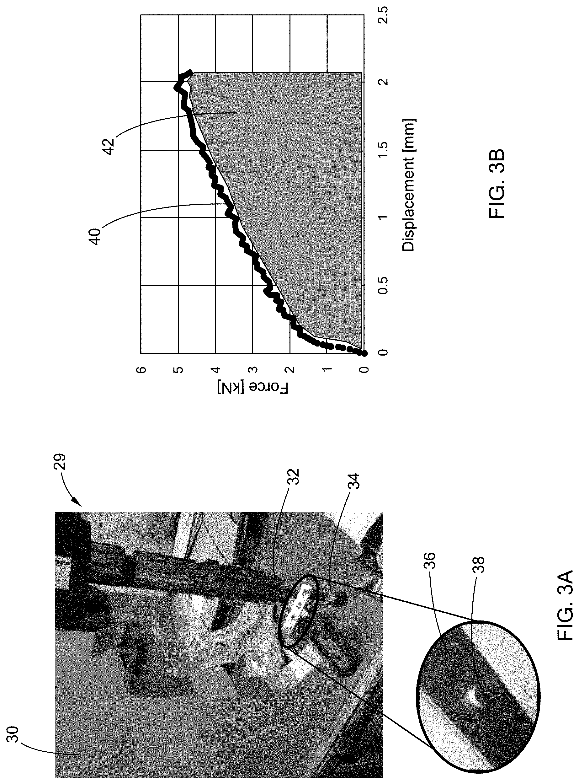
[0028] FIG. 3A illustrates an exemplary clinch testing apparatus used to correlate heat treatment and their respective rivet-abilities by determining energy absorption to failure, according to the teachings of the present disclosure;
[0029] FIG. 3B is a graph of an exemplary quasi-static force-displacement curve of data from FIG. 3A, according to the teachings of the present disclosure;
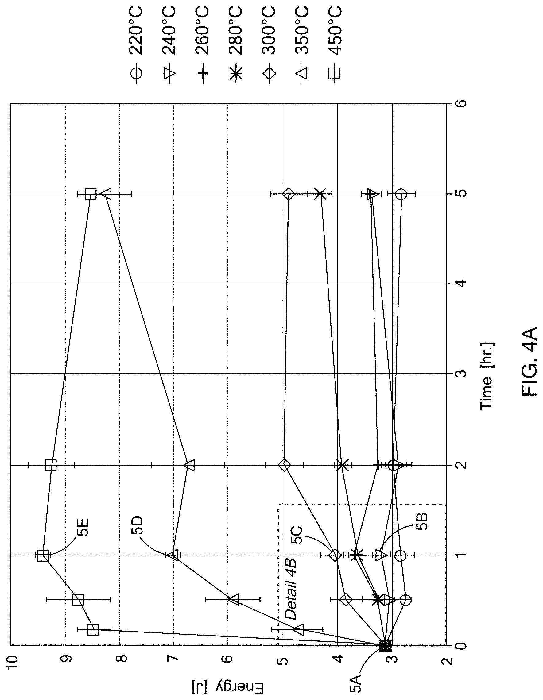
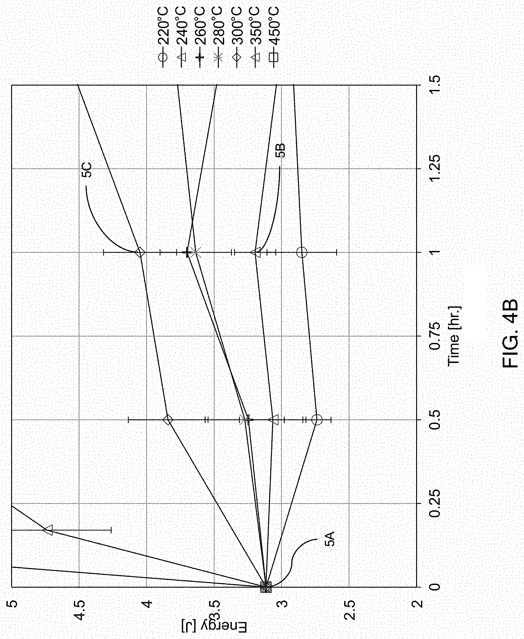
[0030] FIG. 4A includes graphs of an exemplary analyses of measured energy absorbed at failure as a function of time at various temperatures for HPDC aluminum alloy materials, according to the teachings of the present disclosure;
[0031] FIG. 4B is a detail view of FIG. 4A;
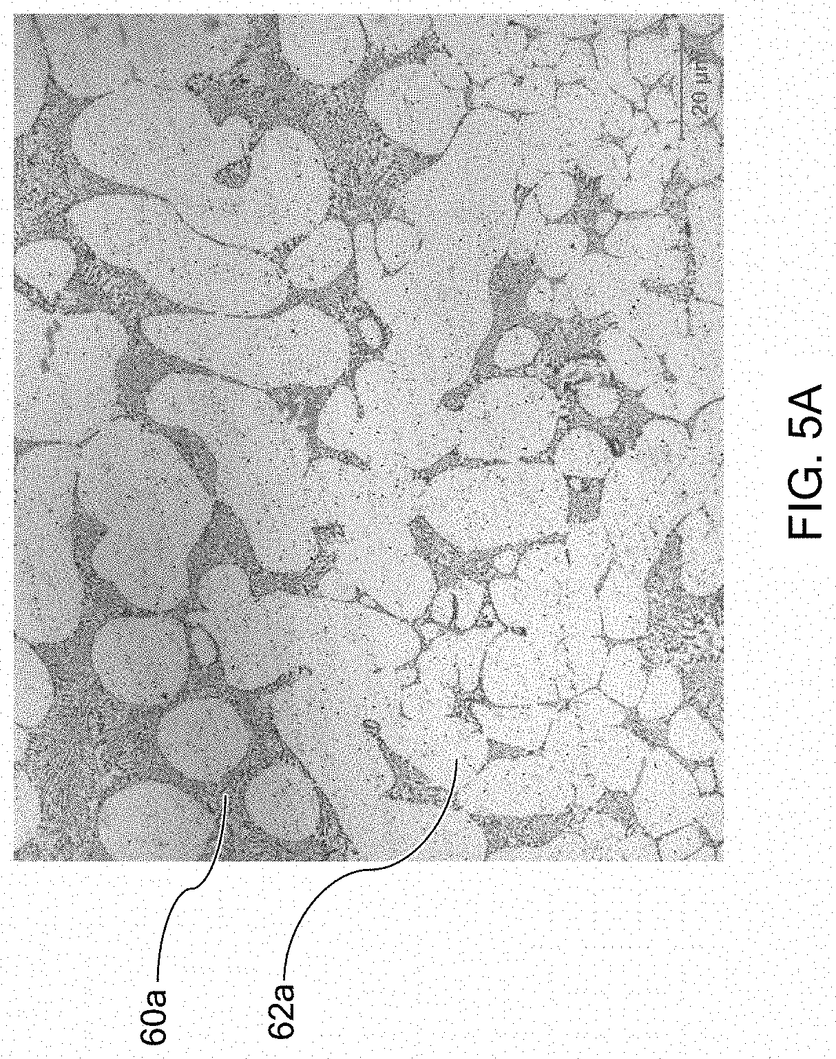
[0032] FIG. 5A is an exemplary optical light microscopy micrograph of the aluminum alloy material of FIG. 4A/4B in the as-cast condition according to the teachings of the present disclosure;
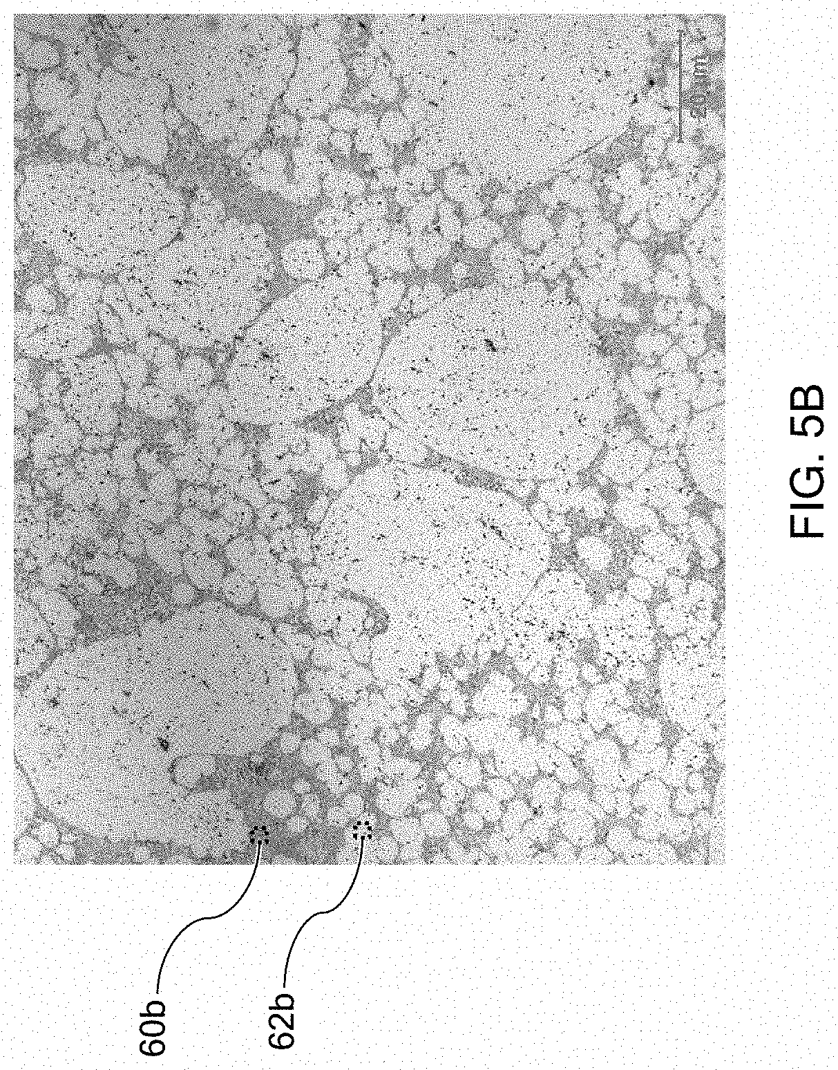
[0033] FIG. 5B is an exemplary optical light microscopy micrograph of the aluminum alloy material of FIG. 4A/4B aged for an hour at 240.degree. C. according to the teachings of the present disclosure;
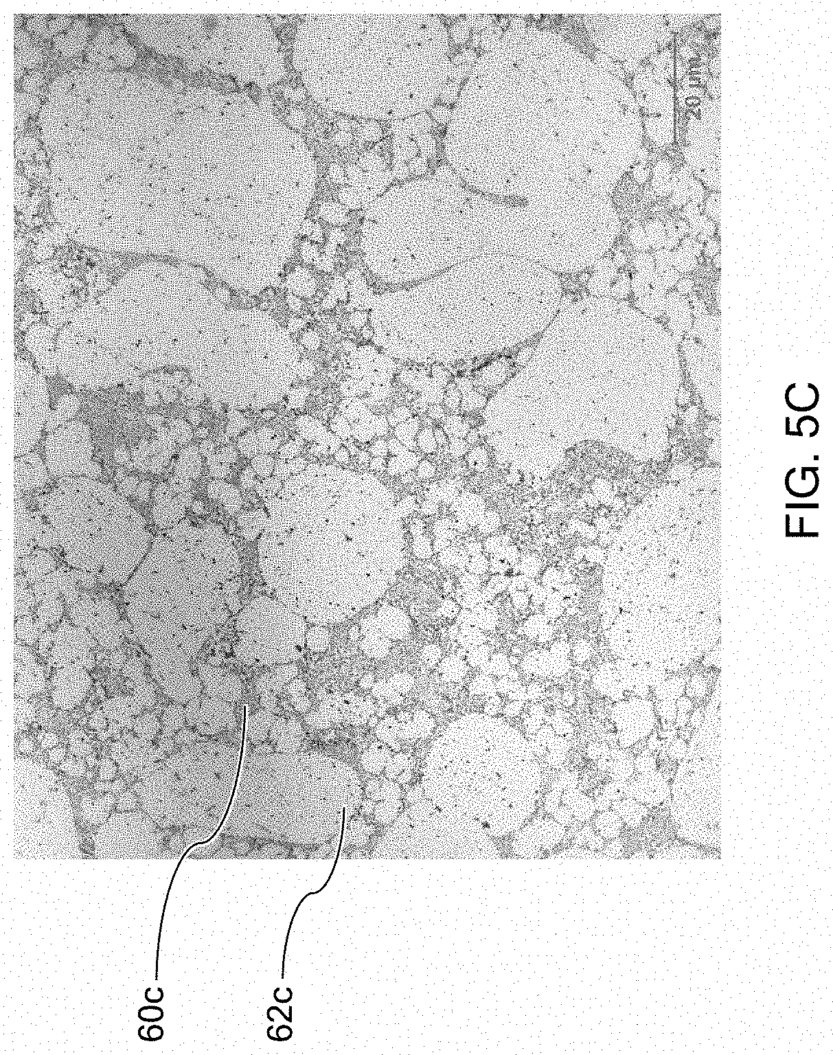
[0034] FIG. 5C is an exemplary optical light microscopy micrograph of the aluminum alloy material of FIG. 4A/4B aged for an hour at 300.degree. C. according to the teachings of the present disclosure;
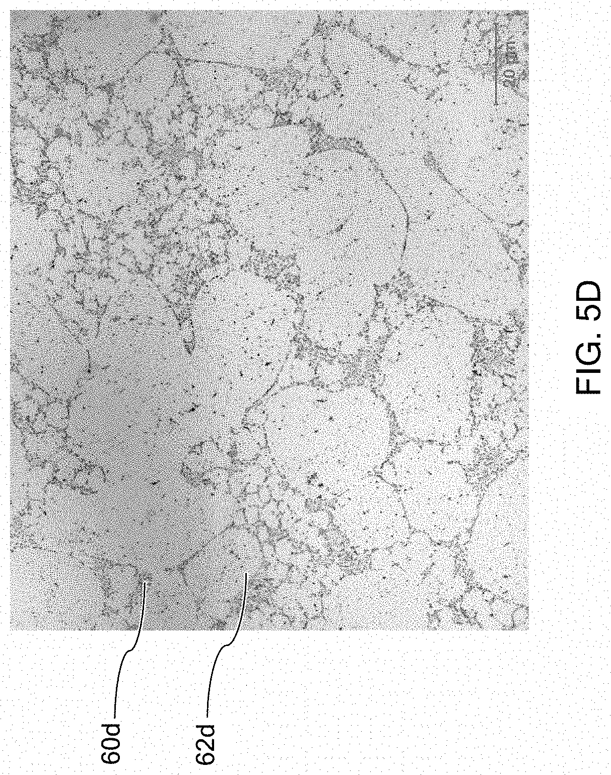
[0035] FIG. 5D is an exemplary optical light microscopy micrograph of the aluminum alloy material of FIG. 4A/4B aged for an hour at 350.degree. C. according to the teachings of the present disclosure;
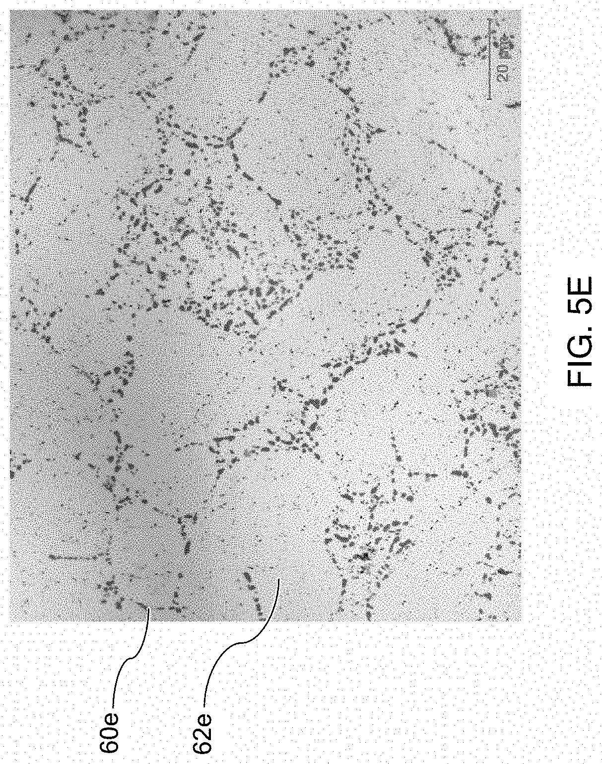
[0036] FIG. 5E is an exemplary optical light microscopy micrograph of the aluminum alloy material of FIG. 4A/4B aged for an hour at 450.degree. C. according to the teachings of the present disclosure;
[0037] FIG. 6 is a flow diagram for an exemplary method of treating a high pressure die cast (HPDC) material to improve rivetability, according to the teachings of the present disclosure;
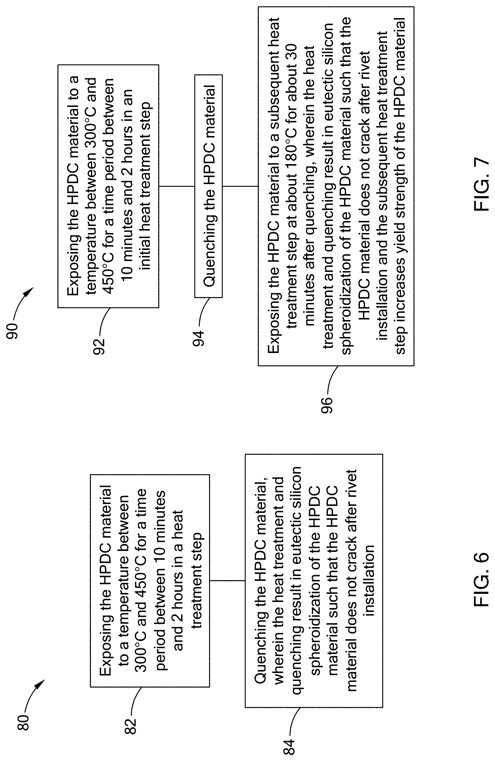
[0038] FIG. 7 is a flow diagram for another exemplary method of treating a high pressure die cast (HPDC) material to improve rivetability, according to the teachings of the present disclosure;
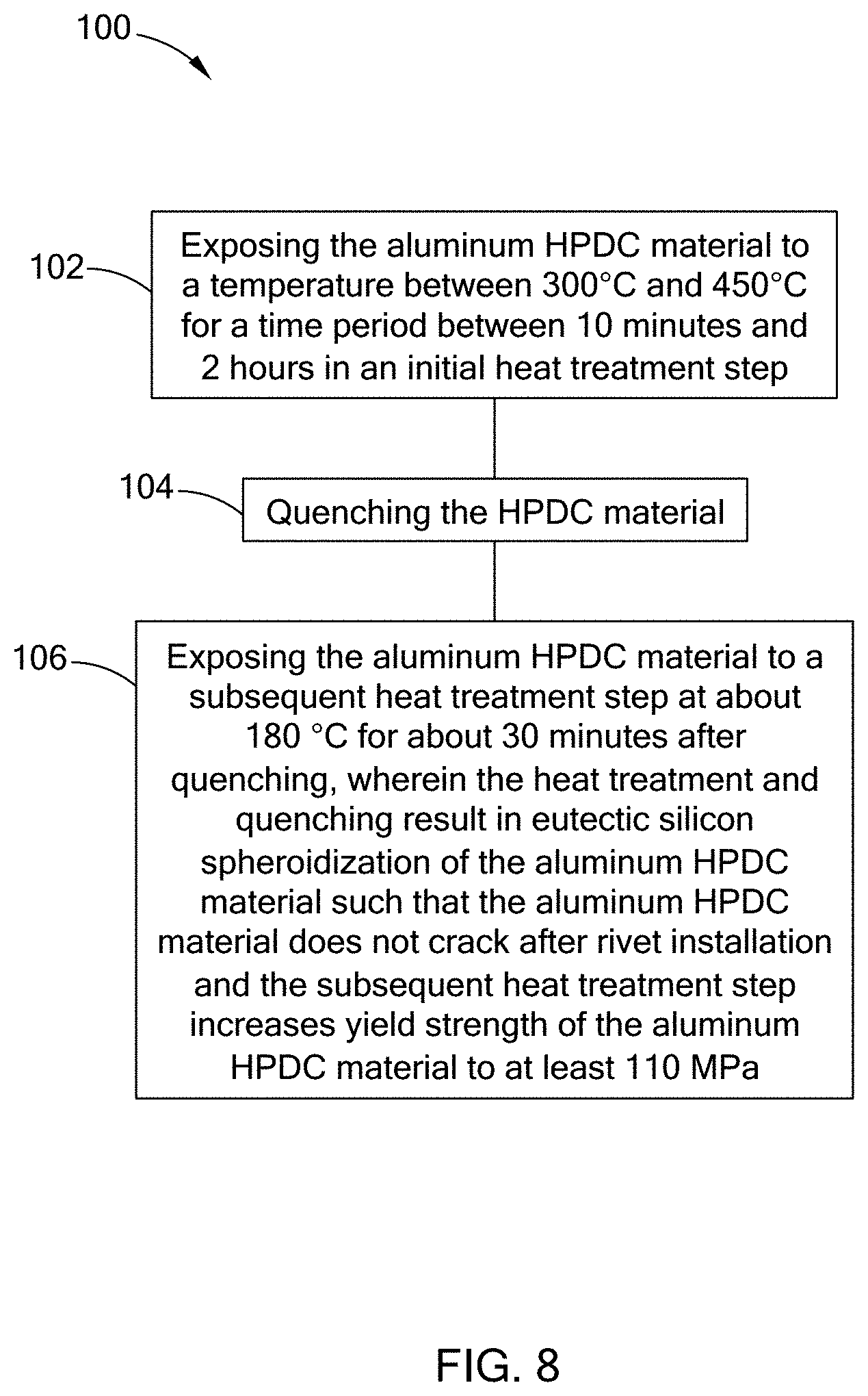
[0039] FIG. 8 is a flow diagram for yet another exemplary method of treating an aluminum high pressure die cast (HPDC) material to improve rivetability, according to the teachings of the present disclosure; and
[0040] FIG. 9 is a histogram graph of the average eutectic silicon particle count per unit area for an exemplary characterization of the spheroidization of eutectic silicon, according to the teachings of the present disclosure.
[0041] The drawings described herein are for illustration purposes only and are not intended to limit the scope of the present disclosure in any way.
DETAILED DESCRIPTION
[0042] The following description is merely exemplary in nature and is not intended to limit the present disclosure, application, or uses. It should be understood that throughout the drawings, corresponding reference numerals indicate like or corresponding parts and features.
[0043] To address the issues of highly localized forming and joining operations on HPDC materials, the present disclosure rivets the parts in the "spheroidized" condition. The present disclosure also stabilizes the castings to address issues with the HPDC aluminum alloys in both the "as-cast" and T5-temper conditions aging at room temperature. The present disclosure further provides an inexpensive mechanical test to characterize and correlate heat treatments to rivetability.
[0044] The inventors have discovered that one method to characterize material rivetability is to assess energy absorption to failure. Factors that contribute to energy absorption include alloy chemistry, temper and thickness, and the energy absorption to failure, which can be determined by piercing a subject material with a cylindrical punch of similar diameter to that of the rivet.
[0045] A clinch test, as shown in FIG. 3A, was developed according to the teachings of the present disclosure. As shown, a test apparatus 29 includes a C-frame 30 with a punch 32, and a sufficiently deep die 34. A test coupon 36 is used, which is shown in the detail view having been deformed by the punch 34.
[0046] Referring now to FIG. 3B, load as a function of displacement from of the test coupon is shown, as a quasi-static force-displacement curve 40. According to general mathematical principles, the area under the curve 42 is the energy absorption to failure, or pierce resistance of the material of the test coupon 36. Accordingly, this clinch test enables rapid assessment of material rivetability on actual parts or material coupons.
[0047] The innovative clinch test correlated new HPDC aluminum alloy heat treatments with their respective rivetabilities by determining energy absorption to failure for a series of time and temperature conditions. Surprisingly, energy absorption was linked to eutectic silicon spheroidization, where energy absorption to failure increases with increasing spheroidization of the silicon eutectic. Therefore, the inventors discovered that a material becomes more rivetable with increasing spheroidization of the silicon eutectic.
[0048] As described in greater detail below, the inventors discovered that temperatures ranging from 300.degree. C. to 450.degree. C. are sufficient to alter the silicon morphology to achieve a higher energy absorption to failure energy, which translates to improved rivetability. Generally, full spheroidization of the silicon eutectic is most rapid at 450.degree. C., taking place within 10-30 mins at temperature. Intermediate spheroidization takes place at 350.degree. C. at times from 30 mins to 2 hours. Partial spheroidization takes place at temperatures of 300.degree. C. after 2-5 hours. Negligible beneficial silicon morphology changes were observed at temperatures less than or equal to 280.degree. C. for the durations of interest to the inventors.
[0049] Now referring to FIGS. 4A and 4B, graphs of measured energy absorbed at failure (i.e. pierce resistance) as a function of time at various temperatures for HPDC aluminum alloy material is provided. (For improved fidelity of certain measurements in FIG. 4A, FIG. 4B is a detail view of a narrower range of values from FIG. 4A). The various times and temperatures evaluated for FIGS. 4A and 4B are recorded below in TABLE 1:
TABLE-US-00001 TABLE 1 Temperature Time Material (.degree. C.) (hours) HPDC 220 0.5 1 2 5 Aluminum 240 0.5 1 2 5 alloy (FIG. 5B) 260 0.5 1 2 5 280 0.5 1 2 5 300 0.5 1 2 5 (FIG. 5C) 350 0.5 1 2 5 (FIG. 5D) 450 0.5 1 2 5 (FIG. 5E)
[0050] Referring now to FIGS. 5A-5E, each of the individual micrographs correspond to the data points 5A through 5E on FIGS. 4A and 4B. FIG. 5A is a micrograph of an HPDC aluminum in the as-received condition showing typical as-cast or F-temper microstructure, containing a fine, nearly continuous interdendritic silicon eutectic phase 60a, surrounded by primary aluminum dendrite phase 62a. FIG. 5B is a micrograph of an HPDC aluminum alloy aged at 240.degree. C. for 1 hour containing a fine, nearly continuous interdendritic silicon eutectic phase 60b, surrounded by primary aluminum dendrites 62b. Further, FIG. 5C is a micrograph of an HPDC aluminum alloy-T5 aged at 300.degree. C. for 1 hour containing partially coarsened or spheroidized eutectic silicon phase 60c surrounded by primary aluminum dendrites. 62c. Meanwhile, FIG. 5D is a micrograph of an HPDC aluminum alloy-T5 aged at 350.degree. C. for 1 hour containing coarsened spheroids of eutectic silicon 60d surrounded by primary aluminum dendrites 62d. Furthermore, FIG. 5E is a micrograph of an HPDC aluminum alloy-T5 aged at 450.degree. C. for 1 hour containing fully spheroidized eutectic silicon phase 60e surrounded by primary aluminum dendrites 62e. Microscopic examination of FIGS. 5A-5E shows the growth of spheroidal eutectic silicon as a function of temperature at a given time.
[0051] Therefore, the inventors have used an HPDC aluminum alloy having a T5 heat treatment, which is attractive due to its commercial availability, and the material does not experience high temperature (>450.degree. C.) solution heat treatment, only a simple aging treatment (220.degree. C.-280.degree. C.) after casting. However, HPDC material in the T5-temper is prone to cracking when mechanically joined. To form a successful SPR button in HPDC aluminum alloys (i.e., no cracking) the material/part must be exposed to temperatures sufficient to spheroidize the silicon morphology within a reasonable amount of time after casting.
[0052] Therefore, the present disclosure provides an improved heat treatment designed to modify silicon morphology to obtain sufficient spheroidization for rivetability. This improved heat treatment includes a eutectic silicon spheroidization step comprising material exposure at a temperature ranging from 300.degree. C. to 450.degree. C. for a time ranging from 10 minutes to 2 hours, as described in greater detail below.
[0053] Furthermore, to mitigate room temperature aging of "as-cast" HPDC materials during storage, the present disclosure exposes the "as-cast" castings to a slightly elevated temperature for a controlled time, thus stabilizing its mechanical properties. This stabilization enables months-long storage of the castings and reduces or negates the room temperature aging of the castings. Castings can thus be stored and eliminate the "expiration date" problem that also is a factor with rolled sheet in the naturally aged condition.
[0054] In one form, the improved heat treatment according to the teachings of the present disclosure also includes a rapid forced air quench. Subsequently, the improved heat treatment includes a paint curing (i.e. paint bake) process at 180.degree. C. for 30 minutes, imparting an additional stabilization heat treatment resulting in a minimum alloy strength of 80 MPa, which is an acceptable strength for most stiffness driven designs.
[0055] In other words, the improved heat treatment of the present disclosure includes a partial solution heat treatment to modify eutectic silicon morphology to achieve high energy absorption to failure energy (i.e. rivetability), while the paint curing stabilizes and modestly improves the strength of the HPDC aluminum alloy. A process for manufacturing an HPDC aluminum alloy part with a temper approximating the aluminum T5-temper according to the teachings of the present disclosure comprises high pressure die casting an aluminum alloy part to form an "as-cast" aluminum alloy part, a partial solution heat-treatment of the "as-cast" aluminum alloy part at about 300.degree. C.-450.degree. C. for about 1-5 hours, and forced air quenching the partially solution heat treated aluminum alloy part. The inventors have found desirable results with forced air quench rates in the range of about 2.degree. C./sec to about 15.degree. C./sec, with an alternate range of about 5.degree. C./sec to about 8.degree. C./sec, and at about 6.degree. C./sec. The process further comprises paint curing the air quenched aluminum alloy part at about 180.degree. C. for about 30 mins. to manufacture an HPDC aluminum alloy part with a temper approximating the aluminum T5-temper, but with improved rivetability.
[0056] As the rivetability of the HPDC aluminum alloy improves, the manufacturability of the HPDC aluminum alloy improves. Improved manufacturability reduces the design margins, manufacturing costs, and part weight. Improved manufacturability also improves fuel efficiency, logistics costs, and lifecycle costs.
[0057] The present disclosure provides a robust production riveting process, followed by an aging process during a coating or sealing process that concurrently ages the HPDC aluminum alloy parts and assemblies analogous to at least a 6XXX series aluminum sheet. The concurrent aging process increases yield strength of the HPDC Aluminum alloy parts, while slightly decreasing ductility, leaving the parts in an approximation of a T5-temper. The loss in ductility negligibly or nominally affects either the assembly process or service characteristics.
[0058] The HPDC aluminum alloy material of the present disclosure comprises the compositional ranges of TABLE 2. The inventors have found desirable results throughout Range A, as well as the alternate Ranges B and C.
TABLE-US-00002 TABLE 2 Range A Max- Range B Range C Minimum imum Min. Max. Min. Max. Element wt. % wt. % wt. % wt. % wt. % wt. % Copper 0.00 0.03 0.00 0.03 0.00 0.03 (Cu) Iron* (Fe) 0.00 0.20 0.00 0.20 0.00 0.20 Magnesium 0.10 0.60 0.25 0.35 0.15 0.25 (Mg) Manganese* 0.45 0.80 0.45 0.55 0.45 0.55 (Mn) Phosphorus 0.00 0.001 0.00 0.001 0.00 0.001 (P) Silicon (Si) 7.00 11.50 9.5 11.50 7.00 8.00 Strontium 0.00 0.03 0.00 0.03 0.00 0.03 (Sr) Titanium 0.00 0.15 0.00 0.15 0.00 0.15 (Ti) Zinc (Zn) 0.00 0.07 0.00 0.07 0.00 0.07 Individual 0.00 0.05 0.00 0.05 0.00 0.05 Impurities Total 0.00 0.15 0.00 0.15 0.00 0.15 Impurities Aluminum ~92 ~86 ~89 ~86 ~92 ~90 (Al) Balance Balance Balance *wt. % Fe + wt. % Mn <0.95
[0059] Referring to FIG. 6, in one form of the present disclosure, a method 80 of treating a high pressure die cast (HPDC) material to improve rivetability is provided. At step 82, the method 80 comprises exposing the HPDC material to a temperature between about 300.degree. C. and about 450.degree. C. for a time period between about 10 minutes and about 5 hours in a heat treatment step. At step 84, the method 80 comprises quenching the HPDC material. In this method 80, the heat treatment results in eutectic silicon spheroidization of the HPDC material such that the HPDC material does not crack after rivet installation.
[0060] In one method of the present disclosure, the method further comprises the step of exposing the HPDC material to a subsequent heat treatment step at about 350.degree. C. for about 30 minutes after quenching. In another method of the present disclosure, the subsequent heat treatment step results in a yield strength of at least about 80 MPa for an aluminum alloy.
[0061] In one form, the eutectic silicon spheroidization comprises fewer than about 3.50.times.10{circumflex over ( )}5 silicon particles per mm{circumflex over ( )}2 in any of the Al--Si eutectic microstructural constituents of an HPDC material.
[0062] In another form, the temperature of the heat treatment step is about 450.degree. C. and the time period is between about 10-30 minutes to result in full spheroidization of silicon eutectic, wherein there are fewer than an average of about 1.50.times.10{circumflex over ( )}5 silicon particles per mm{circumflex over ( )}2 in any of the Al--Si eutectic microstructural constituents of an HPDC material.
[0063] In yet another form, the temperature of the heat treatment step is between about 300.degree. C. to about 450.degree. C. and the time period is between about 30 minutes to about 2 hours to result in intermediate spheroidization of silicon eutectic, wherein there are between about 3.50.times.10{circumflex over ( )}5 and about 1.50.times.10{circumflex over ( )}5 silicon particles per mm{circumflex over ( )}2 in any of the Al--Si eutectic microstructural constituents of an HPDC material.
[0064] In still another form, the temperature of the heat treatment step is about 300.degree. C. and the time period is between about 2 to about 5 hours to result in partial spheroidization of silicon eutectic, wherein there are fewer than an average of about 3.50.times.10{circumflex over ( )}5 silicon particles per mm{circumflex over ( )}2 in any of the Al--Si eutectic microstructural constituents of an HPDC material.
[0065] Now referring to FIG. 7, in another form of the present disclosure, a method 90 of treating a high pressure die cast (HPDC) material to improve rivetability is provided. At step 92, the method 90 comprises exposing the HPDC material to a temperature between about 300.degree. C. and about 450.degree. C. for a time period between about 10 minutes and about 2 hours in an initial heat treatment step. At step 94, the method 90 comprises quenching the HPDC material. At step 96, the method 90 comprises exposing the HPDC material to a subsequent heat treatment step at about 180.degree. C. for about 30 minutes after quenching. In this method of the present disclosure, the heat treatment results in eutectic silicon spheroidization of the HPDC material such that the HPDC material does not crack after rivet installation and the subsequent heat treatment step increases yield strength of the HPDC material.
[0066] Referring to FIG. 8, a method 100 of treating an aluminum high pressure die cast (HPDC) material to improve rivetability is provided. At step 102, the method 100 comprises exposing the aluminum HPDC material to a temperature between about 300.degree. C. and about 450.degree. C. for a time period between about 10 minutes and about 2 hours in an initial heat treatment step. At step 104, the method 100 comprises quenching the aluminum HPDC material. At step 106, the method 100 comprises exposing the aluminum HPDC material to a subsequent heat treatment step at about 180.degree. C. for about 30 minutes after quenching. In this method of the present disclosure, the heat treatment results in eutectic silicon spheroidization of the aluminum HPDC material such that the aluminum HPDC material does not crack after rivet installation and the subsequent heat treatment step increases yield strength of the aluminum HPDC material to at least about 80 MPa.
[0067] Characterization of Spheroidization of Eutectic Silicon
[0068] With reference to FIG. 9, metallographic samples of an aluminum HPDC alloy were prepared to characterize the spheroidization of eutectic silicon as a function of time and temperature. The metallographic samples were from three different tempering conditions while the time at temperature was held constant. The three tempering conditions were (1) F-Temper (as-cast Condition), (2) 350.degree. C.-2 Hr (F-Temper followed by a spheroidization heat treatment at 350.degree. C. for 2 hours), and (3) 450.degree. C.-2 Hr (F-Temper followed by a spheroidization heat treatment at 450.degree. C. for 2 hours). Micrographs with suitable contrast between the eutectic silicon phase and the aluminum phase are taken of the samples at about 1000.times. magnification for this analysis. An image analysis program counts the dark inter-dendritic silicon particles (Si particle count). Spatial calibration converts the pixel area of the micrograph to an equivalent area (mm{circumflex over ( )}2) to determine the number of Si particles per unit area (Si particle count/mm{circumflex over ( )}2). This characterization process was repeated 10 times for each material condition. Image analysis results for an exemplary Al--Si--Mg--Mn HPDC Al alloy at three material conditions are reported in TABLE 3 and graphed in FIG. 9. As the silicon count per unit area decreases the rivetability increases and conversely as the silicon count per unit area increases the rivetability decreases. The reduction in silicon count per unit area is due to the spheroidization or coarsening of the silicon.
TABLE-US-00003 TABLE 3 F-Temper 350.degree. C.-2 Hr 450.degree. C.-2 Hr Si particle Si particle Si particle Si particle Si particle Si particle Micrograph # count count/mm{circumflex over ( )}2 count count/mm{circumflex over ( )}2 count count/mm{circumflex over ( )}2 1 9.4E+03 4.7E+05 4.8E+03 2.4E+05 2.0E+03 9.9E+04 2 9.8E+03 5.0E+05 4.5E+03 2.3E+05 1.9E+03 9.4E+04 3 7.9E+03 4.0E+05 5.5E+03 2.8E+05 2.1E+03 1.1E+05 4 7.4E+03 3.8E+05 4.7E+03 2.4E+05 2.0E+03 9.9E+04 5 1.0E+04 5.3E+05 5.6E+03 2.8E+05 2.5E+03 1.3E+05 6 6.9E+03 3.5E+05 5.4E+03 2.7E+05 3.0E+03 1.5E+05 7 7.9E+03 4.0E+05 3.7E+03 1.9E+05 1.7E+03 8.4E+04 8 8.8E+03 4.5E+05 5.0E+03 2.5E+05 2.2E+03 1.1E+05 9 8.4E+03 4.3E+05 4.1E+03 2.0E+05 1.6E+03 8.1E+04 10 8.6E+03 4.4E+05 3.6E+03 1.8E+05 1.7E+03 8.5E+04 Maximum 1.0E+04 5.3E+05 5.6E+03 2.8E+05 3.0E+03 1.5E+05 Mean 8.6E+03 4.3E+05 4.7E+03 2.4E+05 2.1E+03 1.0E+05 Median 8.5E+03 4.3E+05 4.7E+03 2.4E+05 2.0E+03 9.9E+04 Minimum 6.9E+03 3.5E+05 3.6E+03 1.8E+05 1.6E+03 8.1E+04 Std. dev 1.1E+03 5.5E+04 7.2E+02 3.7E+04 4.3E+02 2.2E+04 Dimensions of micrograph at 1000X magnification: 2048 pixels .times. 2448 pixels 5013504 pixels{circumflex over ( )}2 19779 .mu.m{circumflex over ( )}2 0.019779 mm{circumflex over ( )}2
[0069] Unless otherwise expressly indicated herein, all numerical values indicating mechanical/thermal properties, compositional percentages, dimensions and/or tolerances, or other characteristics are to be understood as modified by the word "about" or "approximately" in describing the scope of the present disclosure. This modification is desired for various reasons including industrial practice, manufacturing technology, and testing capability.
[0070] The description of the disclosure is merely exemplary in nature and, thus, variations that do not depart from the substance of the disclosure are intended to be within the scope of the disclosure. Such variations are not to be regarded as a departure from the spirit and scope of the disclosure.
* * * * *
D00001
D00002
D00003
D00004
D00005
D00006
D00007
D00008
D00009
D00010
D00011
D00012
D00013

XML
uspto.report is an independent third-party trademark research tool that is not affiliated, endorsed, or sponsored by the United States Patent and Trademark Office (USPTO) or any other governmental organization. The information provided by uspto.report is based on publicly available data at the time of writing and is intended for informational purposes only.
While we strive to provide accurate and up-to-date information, we do not guarantee the accuracy, completeness, reliability, or suitability of the information displayed on this site. The use of this site is at your own risk. Any reliance you place on such information is therefore strictly at your own risk.
All official trademark data, including owner information, should be verified by visiting the official USPTO website at www.uspto.gov. This site is not intended to replace professional legal advice and should not be used as a substitute for consulting with a legal professional who is knowledgeable about trademark law.