Cargo Handling Pallet
TSURUTA; Takashi
U.S. patent application number 16/308045 was filed with the patent office on 2019-10-10 for cargo handling pallet. This patent application is currently assigned to Advanced Logi-Tech Japan Co., Ltd.. The applicant listed for this patent is ADVANCED LOGI-TECH JAPAN CO., LTD.. Invention is credited to Takashi TSURUTA.
| Application Number | 20190308770 16/308045 |
| Document ID | / |
| Family ID | 59081983 |
| Filed Date | 2019-10-10 |


View All Diagrams
| United States Patent Application | 20190308770 |
| Kind Code | A1 |
| TSURUTA; Takashi | October 10, 2019 |
CARGO HANDLING PALLET
Abstract
A cargo handling pallet includes: a cargo placement surface, and a ground contact surface parallel with the placement surface and in contact with a pallet supporting surface. At least one of four edges of the placement surface is formed as an eaves edge over the entire length or a part of the length. A recess is defined below the eaves edge such that the pallet supporting surface is exposed by the recess, and a distal end of a fork can be inserted into the recess. The eaves edge has a sliding contact portion that is brought into sliding contact with an upper surface of the distal end of the fork. The depth of the recess is set longer than the fork insertion length for a case where the upper surface of the distal end of the fork is first brought into contact with the sliding contact portion.
| Inventors: | TSURUTA; Takashi; (Tokyo, JP) | ||||||||||
| Applicant: |
|
||||||||||
|---|---|---|---|---|---|---|---|---|---|---|---|
| Assignee: | Advanced Logi-Tech Japan Co.,
Ltd. Tokyo JP |
||||||||||
| Family ID: | 59081983 | ||||||||||
| Appl. No.: | 16/308045 | ||||||||||
| Filed: | May 31, 2017 | ||||||||||
| PCT Filed: | May 31, 2017 | ||||||||||
| PCT NO: | PCT/JP2017/020248 | ||||||||||
| 371 Date: | December 7, 2018 |
| Current U.S. Class: | 1/1 |
| Current CPC Class: | B65D 2519/00059 20130101; B65D 2519/00343 20130101; B65D 2519/00796 20130101; B65D 19/0002 20130101; B65D 2519/00407 20130101; B65D 2519/00024 20130101; B65D 2519/00288 20130101; B65D 2519/00064 20130101; B65D 19/0014 20130101; B65D 2519/00268 20130101; B65D 2519/00029 20130101; B65D 2519/00338 20130101; B65D 2519/00412 20130101; B65D 2519/00054 20130101; B65D 2519/00019 20130101; B65D 2519/00308 20130101; B65D 2519/00069 20130101; B65D 2519/00363 20130101; B65D 2519/00034 20130101; B65D 2519/00318 20130101 |
| International Class: | B65D 19/00 20060101 B65D019/00 |
Foreign Application Data
| Date | Code | Application Number |
|---|---|---|
| Jul 25, 2016 | JP | 2016-145721 |
Claims
1. A cargo handling pallet for use in cargo handling work that is carried out with a forklift truck equipped with a fork having an upper surface of a distal end inclined downward to a tip, the cargo handling pallet comprising: a placement surface having a rectangular plate shape on which cargo is placed; and a ground contact surface parallel with the placement surface and in contact with a pallet supporting surface, wherein at least one of four edges of the placement surface is formed as an eaves edge over an entire length or a part of the length, a recess is defined below the eaves edge such that the pallet supporting surface is exposed by the recess, and that the distal end of the fork is inserted into the recess, whereas a fork insertion space is not provided inside the cargo handling pallet, the eaves edge has, on a lower surface of the eaves edge, a sliding contact portion that is brought into sliding contact with the upper surface of the distal end of the fork, and the eaves edge is raised due to the sliding contact between the sliding contact portion and the upper surface of the distal end of the fork, such that a fork insertion gap appears between the ground contact surface and the pallet supporting surface that has been in contact with the ground contact surface.
2. The cargo handling pallet according to claim 1, wherein the lower surface of the eaves edge is inclined downward to the inside of the pallet.
3. The cargo handling pallet according to claim 2, wherein the lower surface of the eaves edge includes an inclined plane.
4. The cargo handling pallet according to claim 2, wherein the lower surface of the eaves edge includes an inclined convex surface, a plurality of inclined steps, or an inclined bent surface.
5. The cargo handling pallet according to claim 2, wherein a lower end of the inclined lower surface of the eaves edge is connected to the ground contact surface.
6. The cargo handling pallet according to claim 2, wherein a lower end of the inclined lower surface of the eaves edge is set higher than the ground contact surface, such that a raised wall connecting the lower end of the lower surface of the eaves edge and the ground contact surface is formed.
7. The cargo handling pallet according to claim 2, wherein a lower end of the inclined lower surface of the eaves edge is set higher than the ground contact surface, such that a groove is formed in the ground contact surface so as to continue from the lower end of the lower surface of the eaves edge and extend a depth of the recess.
8. The cargo handling pallet according to claim 1, wherein a plurality of penetrating or bottomed lightening portions is provided in the placement surface and the ground contact surface.
9. The cargo handling pallet according to claim 3, wherein a lower end of the inclined lower surface of the eaves edge is connected to the ground contact surface.
10. The cargo handling pallet according to claim 4, wherein a lower end of the inclined lower surface of the eaves edge is connected to the ground contact surface.
11. The cargo handling pallet according to claim 3, wherein a lower end of the inclined lower surface of the eaves edge is set higher than the ground contact surface, such that a raised wall connecting the lower end of the lower surface of the eaves edge and the ground contact surface is formed.
12. The cargo handling pallet according to claim 4, wherein a lower end of the inclined lower surface of the eaves edge is set higher than the ground contact surface, such that a raised wall connecting the lower end of the lower surface of the eaves edge and the ground contact surface is formed.
13. The cargo handling pallet according to claim 3, wherein a lower end of the inclined lower surface of the eaves edge is set higher than the ground contact surface, such that a groove is formed in the ground contact surface so as to continue from the lower end of the lower surface of the eaves edge and extend a depth of the recess.
14. The cargo handling pallet according to claim 4, wherein a lower end of the inclined lower surface of the eaves edge is set higher than the ground contact surface, such that a groove is formed in the ground contact surface so as to continue from the lower end of the lower surface of the eaves edge and extend a depth of the recess.
15. The cargo handling pallet according to claim 2, wherein a plurality of penetrating or bottomed lightening portions is provided in the placement surface and the ground contact surface.
16. The cargo handling pallet according to claim 3, wherein a plurality of penetrating or bottomed lightening portions is provided in the placement surface and the ground contact surface.
17. The cargo handling pallet according to claim 4, wherein a plurality of penetrating or bottomed lightening portions is provided in the placement surface and the ground contact surface.
18. The cargo handling pallet according to claim 5, wherein a plurality of penetrating or bottomed lightening portions is provided in the placement surface and the ground contact surface.
19. The cargo handling pallet according to claim 6, wherein a plurality of penetrating or bottomed lightening portions is provided in the placement surface and the ground contact surface.
20. The cargo handling pallet according to claim 7, wherein a plurality of penetrating or bottomed lightening portions is provided in the placement surface and the ground contact surface.
Description
TECHNICAL FIELD
[0001] The present invention relates to a cargo handling pallet that serves as a platform on which cargo is placed during cargo handling work such as cargo loading, unloading, and conveying.
BACKGROUND ART
[0002] This type of cargo handling pallet is premised on that the cargo handling pallet is scooped up, raised, lowered, or conveyed together with cargo using a fork (claw) of a forklift truck inserted into the cargo handling pallet, and thereafter the fork is removed from the cargo handling pallet. Therefore, how the fork can be smoothly inserted and removed is an important factor of the cargo handling pallet.
[0003] Conventionally, a rectangular thick plate-like cargo handling pallet called a conventional pallet ("flat pallet" in Japan) is the most prevalent type of cargo handling pallet. This pallet includes a placement surface on which cargo is placed and a ground contact surface that is in contact with a pallet supporting surface such as the ground, and a fork pocket (fork insertion space) is formed between the placement surface and the ground contact surface so that a fork can be inserted and removed with a margin (for example, refer to FIG. 1 of Patent Literature 1 below).
[0004] The conventional pallet is advantageous in that the fork can be smoothly inserted and removed owing to the presence of the fork pocket. However, in order to form the fork pocket of a sufficient size while ensuring the strength, the pallet needs to have a thickness of 120 to 200 mm, which is several times the thickness of the fork (typical fork has a thickness of about 45 mm). Therefore, the conventional pallet has a large volume due to the thickness of the pallet, and erodes the capacity of a container or warehouse, leading to a decrease in cargo loading efficiency.
[0005] In this regard, as disclosed in Patent Literature 1 below, a cargo handling pallet formed as thin as possible without a fork pocket has been developed. The cargo handling pallet of Patent Literature 1 is made of plywood having a thickness of 2.5 to 5.5 mm, has a placement surface on the front side and a ground contact surface on the back side, and is configured to include an inclined piece rising and extending obliquely from at least one of four edges of the placement surface.
CITATION LIST
Patent Literature
[0006] Patent Literature 1: JP 60-13333 Y
SUMMARY OF INVENTION
Technical Problem
[0007] Since the cargo handling pallet of Patent Literature 1 has a small thickness, the pallet itself can have a reduced volume. However, the inclined piece extending from the placement surface causes the following problem: An unnecessary space is generated on the inclined piece where cargo cannot be placed. For this reason, the loading efficiency has not been greatly improved yet.
[0008] In addition, according to the cargo handling pallet of Patent Literature 1, the fork needs to be inserted between the ground contact surface and the pallet supporting surface such as a floor and the ground while the inclined piece is grasped and drawn by a push-pull device (paragraph 2 of page 8 and FIG. 8). This causes the following problem: The complicated work of simultaneously operating the push-pull device and the fork results in extremely poor work efficiency, as compared with the work that is carried out only with the fork.
[0009] In a case where the cargo handling pallet of Patent Literature 1 exists on the floor or on the ground, that is, on the pallet supporting surface extending in front of the inclined piece, if the fork, typified by a fork incorporating a roller conveyor (roller fork), whose upper surface of a distal end is inclined downward to a tip, is accurately operated, the fork can be inserted between the ground contact surface and the pallet supporting surface without using the push-pull device.
[0010] However, in a case where a plurality of cargoes is stacked using the cargo handling pallet of Patent Literature 1, and the pallet on the second or higher stage is to be handled, the ground contact surface of the pallet and the pallet supporting surface (top surface of the lower cargo) have substantially the same area, and coincide and overlap with each other. Therefore, the pallet supporting surface cannot be visually checked, making it difficult to determine to what extent the distal end of the fork is to be moved. Accordingly, it is obviously difficult to insert the fork between the ground contact surface of the pallet on the second or higher stage and the pallet supporting surface, and the lower cargo is liable to be damaged.
[0011] As described above, although the volume of the cargo handling pallet of Patent Literature 1 is small owing to the small thickness of the pallet, a significant improvement in the loading efficiency cannot be expected due to the presence of the unnecessary space where cargo cannot be placed. In addition, the cargo handling work must be carried out, in principle, through the simultaneous operation for the push-pull device and the fork, resulting in poor work efficiency. Even with the use of a special fork such as the roller fork whose upper surface of the distal end is inclined downward, it is difficult to handle the cargo on the second or higher stage among the plurality of stacked cargoes.
Solution to Problem
[0012] The present invention drastically solves the problems related to the conventional cargo handling pallet, and provides an unparalleled cargo handling pallet which improves both the loading efficiency and the work efficiency.
[0013] In summary, the cargo handling pallet according to the present invention is based on the premise that it is used for cargo handling work that is carried out with a forklift truck equipped with a fork having an upper surface of a distal end inclined downward to a tip, and the cargo handling pallet has the following configuration.
[0014] Specifically, the cargo handling pallet includes: a placement surface having a rectangular plate shape on which cargo is placed; and a ground contact surface parallel with the placement surface and in contact with a pallet supporting surface. At least one of four edges of the placement surface is formed as an eaves edge over the entire length or a part of the length. A recess is defined below the eaves edge such that the pallet supporting surface is exposed by the recess, and that the distal end of the fork is inserted into the recess, whereas a fork insertion space is not provided inside the cargo handling pallet. The eaves edge has, on a lower surface of the eaves edge, a sliding contact portion that is brought into sliding contact with the upper surface of the distal end of the fork, and the eaves edge is raised due to the sliding contact between the sliding contact portion and the upper surface of the distal end of the fork, such that a fork insertion gap appears between the ground contact surface and the pallet supporting surface that has been in contact with the ground contact surface.
[0015] Preferably, the lower surface of the eaves edge is configured to be inclined downward to the inside of the pallet, whereby the lower surface can be smoothly brought into sliding contact with the upper surface of the distal end of the fork, and the proximal end (inner end) side of the eaves edge can be reinforced.
[0016] More preferably, the lower surface of the eaves edge is configured to include an inclined convex surface, a plurality of inclined steps, or an inclined bent surface, whereby the sliding contact portion is provided so as to be reliably brought into sliding contact with the upper surface of the distal end of the fork. The lower surface of the eaves edge is configured to include an inclined plane, whereby the visibility of the pallet supporting surface through the recess is improved using a simple structure.
[0017] A lower end of the inclined lower surface of the eaves edge is configured to be connected to the ground contact surface, whereby the recess is formed so that the strength of the eaves edge is increased.
[0018] Alternatively, the lower end of the inclined lower surface of the eaves edge is set higher than the ground contact surface, such that a raised wall connecting the lower end of the lower surface of the eaves edge and the ground contact surface is formed, whereby the depth of the recess can be made as long as possible.
[0019] Alternatively, the lower end of the inclined lower surface of the eaves edge is set higher than the ground contact surface, such that a groove is formed in the ground contact surface so as to continue from the lower end of the lower surface of the eaves edge and extend the depth of the recess, whereby the depth of the recess is further extended by the groove, and the inserted fork is prevented from being displaced in the lateral direction.
[0020] Preferably, a plurality of penetrating or bottomed lightening portions is provided in the placement surface and the ground contact surface, whereby the weight is reduced. This configuration also enables nesting during nonuse.
Advantageous Effects of Invention
[0021] According to the cargo handling pallet of the present invention, a space into/from which the entire fork can be inserted/removed such as a conventional fork pocket does not need to be provided inside the pallet, and only the recess into which the distal end of the fork is inserted needs to be formed below the edge of the placement surface. Therefore, the thickness of the pallet can be made as small as possible.
[0022] In addition, the placement surface can be effectively utilized since an unnecessary space where cargo cannot be placed is not generated around the placement surface.
[0023] Moreover, the eaves edge of the placement surface and the recess defined below the eaves edge cooperate with each other, so that the fork can be smoothly inserted between the ground contact surface and the pallet supporting surface. Therefore, the cargo handling work can be carried out only with the fork.
[0024] Furthermore, the cargo handling work can be carried out while the pallet supporting surface is visually checked through the recess. Therefore, the cargo handling work can be efficiently carried out, in particular, on the cargo on the second or higher stage among the plurality of stacked cargoes.
[0025] Thus, according to the cargo handling pallet of the present invention, an improvement in the efficiency of loading cargo into a container or warehouse and an improvement in the work efficiency of the cargo handling work can be achieved in a highly successful manner.
BRIEF DESCRIPTION OF DRAWINGS
[0026] FIG. 1A is a perspective view illustrating a cargo handling pallet according to Example 1 viewed from the placement surface side.
[0027] FIG. 1B is a perspective view illustrating the cargo handling pallet according to Example 1 viewed from the ground contact surface side.
[0028] FIG. 2 is a perspective view of a fork.
[0029] FIG. 3 is an enlarged explanatory view of a distal end of the fork.
[0030] FIG. 4A is an enlarged explanatory view illustrating a state in which a sliding contact portion of a lower surface of an eaves edge is in contact with an upper surface of the distal end of the fork.
[0031] FIG. 4B is an enlarged explanatory view illustrating a state in which the eaves edge is raised after the sliding contact portion of the lower surface of the eaves edge is brought into sliding contact with the upper surface of the distal end of the fork.
[0032] FIG. 5A is an enlarged explanatory view illustrating the eaves edge having the lower surface including an inclined convex surface.
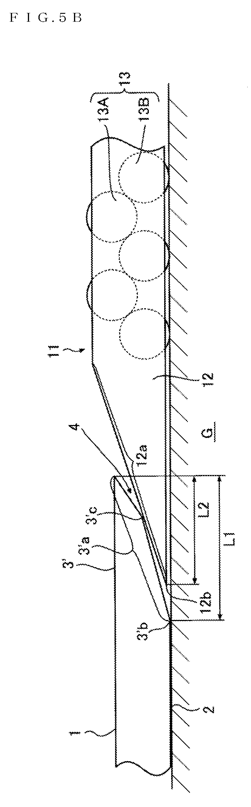
[0033] FIG. 5B is an enlarged explanatory view illustrating the eaves edge having the lower surface including an inclined bent surface.
[0034] FIG. 6A is an enlarged explanatory view illustrating the eaves edge having the lower surface including a plurality of steps.
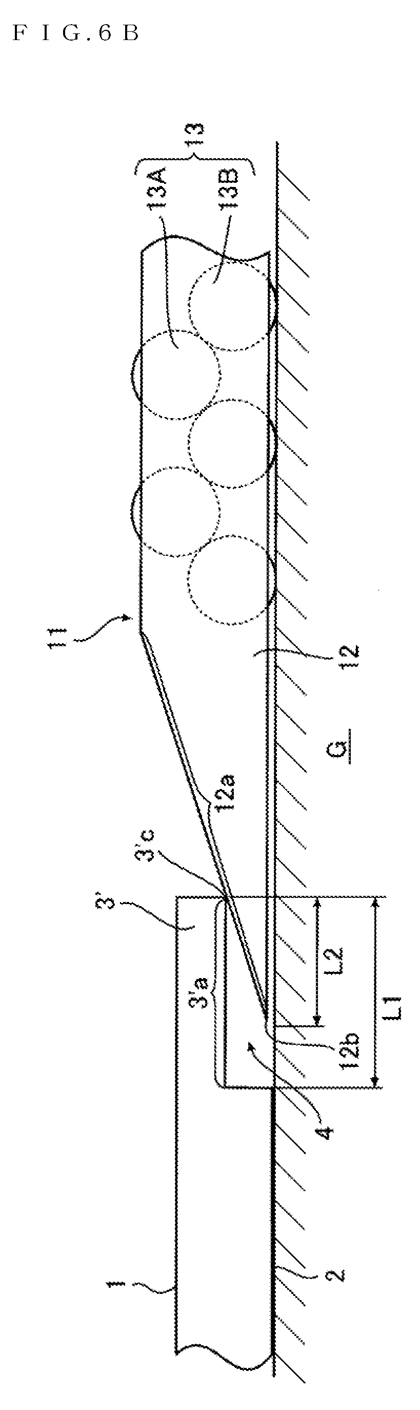
[0035] FIG. 6B is an enlarged explanatory view illustrating the eaves edge having the lower surface which is not inclined.
[0036] FIG. 7A is an enlarged explanatory view illustrating an example of a lower end of the lower surface of the eaves edge which is set higher than the ground contact area.
[0037] FIG. 7B is an enlarged explanatory view illustrating another example of the configuration illustrated in FIG. 7A.
[0038] FIG. 8 is a perspective view illustrating a plurality of stacked cargoes.
[0039] FIG. 9A is a perspective view illustrating a cargo handling pallet according to Example 2 viewed from the placement surface side.
[0040] FIG. 9B is a perspective view illustrating the cargo handling pallet according to Example 2 viewed from the ground contact surface side.
[0041] FIG. 10A is a perspective view illustrating a cargo handling pallet according to Example 3 viewed from the placement surface side.
[0042] FIG. 10B is a perspective view illustrating the cargo handling pallet according to Example 3 viewed from the ground contact surface side.
[0043] FIG. 11A is a perspective view illustrating a cargo handling pallet according to Example 4 viewed from the placement surface side.
[0044] FIG. 11B is a perspective view illustrating the cargo handling pallet according to Example 4 viewed from the ground contact surface side.
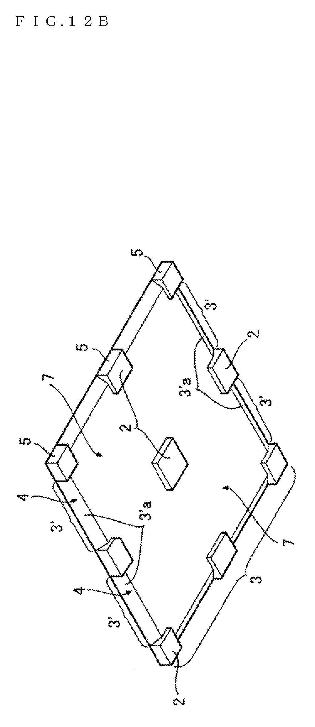
[0045] FIG. 12A is an enlarged explanatory view illustrating an example of the lower end of the lower surface of the eaves edge which is set higher than the ground contact area to form a groove in the ground contact surface.
[0046] FIG. 12B is a perspective view illustrating the cargo handling pallet according to the example of FIG. 12A viewed from the ground contact surface side.
[0047] FIG. 13A is a perspective view illustrating a cargo handling pallet according to Example 5 viewed from the placement surface side.
[0048] FIG. 13B is a perspective view illustrating the cargo handling pallet according to Example 5 viewed from the ground contact surface side.
[0049] FIG. 14A is a perspective view illustrating a cargo handling pallet according to Example 6 viewed from the placement surface side.
[0050] FIG. 14B is a perspective view illustrating the cargo handling pallet according to Example 6 viewed from the ground contact surface side.
[0051] FIG. 15 is a cross-sectional view of the cargo handling pallet according to Example 6.
DESCRIPTION OF EMBODIMENTS
[0052] Hereinafter, optimal examples of a cargo handling pallet according to the present invention will be described with reference to FIGS. 1A to 15.
<Basic Configuration>
[0053] As illustrated in FIGS. 1A, 1B, 9A, 9B, 10A, 10B, 11A, 11B, 13A, 13B, 14A, and 14B, a cargo handling pallet according to the present invention has a rectangular plate shape, and includes a placement surface 1 on which cargo is placed and a ground contact surface 2 parallel with the placement surface 1 and in contact with a pallet supporting surface such as the ground, a floor, and a top surface of a lower cargo. At least one of four edges (sides) 3 of the placement surface 1 is formed as an eaves edge 3' over the entire length or apart of the length, and a recess 4 is defined below the eaves edge 3'.
[0054] Specifically a corner angle between a side surface 5 and the ground contact surface 2 is removed, whereby the recess 4 is defined below the eaves edge 3'. The recess 4 is therefore a space open in the lateral and downward directions. The pallet supporting surface is exposed by the recess 4, and a distal end 12 of a fork 11 to be described later is inserted into the recess 4.
[0055] The edge 3 of the placement surface 1 which is not formed as the eaves edge 3' is coupled to the ground contact surface 2 via the side surface 5.
[0056] The cargo handling pallet according to the present invention can be formed of a material that is used for a known cargo handling pallet, such as wood, metal, synthetic resin, and paper. Since only the recess 4 into which the distal end of the fork is inserted needs to be formed below the edge 3' of the placement surface 1, the thickness of the pallet can be made as small as possible. For example, the pallet can have a thickness of about 5 to 70 mm, depending on the material. Preferably, the thickness of the pallet is 30 mm in terms of the relation with the strength.
[0057] According to the cargo handling pallet of the present invention, the placement surface 1 can be effectively utilized since an unnecessary space where cargo cannot be placed is not generated around the placement surface 1.
[0058] Therefore, the efficiency of loading cargo into a container or warehouse can be greatly improved.
[0059] The following descriptions of the respective examples are based on the assumption that all the four edges 3 of the placement surface 1 are formed as the eaves edges 3' over the entire length or a part of the length. As described above, however, the present invention encompasses all the configurations in which the eaves edge 3' is formed over the entire length or a part of the length of at least one of the edges 3 of the placement surface 1, and the recess 4 is defined below the eaves edge 3'.
<Premise Configuration>
[0060] Hereinafter, a premise configuration of the cargo handling pallet according to the present invention will be described. The cargo handling pallet according to the present invention is based on the premise that it is used for the cargo handling work that is carried out with a forklift truck equipped with the fork 11 as illustrated in FIGS. 2 and 3. In other words, the cargo handling pallet is based on the premise that the fork 11 having an upper surface 12a of the distal end 12 inclined downward to a tip 12b is inserted and removed.
[0061] The fork 11 having the above-described structure is preferably exemplified by the roller fork 11 incorporating a roller conveyor 13 as illustrated in FIGS. 2 and 3. The roller conveyor 13 incorporated in the roller fork 11 includes a plurality of upper rollers 13A and a plurality of lower rollers 13B. The rollers 13A and 13B rotate in the opposite directions in conjunction with each other, and complement the movement of the fork 11 on a pallet supporting surface G and the loading/unloading of the pallet, cargo, or the like onto/from the fork 11.
[0062] For example, referring to FIG. 3, when the fork 11 is moved in the left direction (fork 11 is moved forward), with the lower rollers 13B in contact with the pallet supporting surface G, the lower rollers 13B accordingly rotate to the left, and the upper rollers 13A accordingly rotate to the right. Consequently, the fork 11 can be smoothly moved forward on the pallet supporting surface G owing to the rotation of the lower rollers 13B, and the pallet, cargo, or the like can be guided onto the fork 11 owing to the rotation of the upper rollers 13A.
[0063] In contrast, when the fork 11 is moved in the right direction (fork 11 is moved backward), with the lower rollers 13B in contact with the pallet supporting surface G, the lower rollers 13B accordingly rotate to the right, and the upper rollers 13A accordingly rotate to the left. Consequently, the fork 11 can be smoothly moved backward on the pallet supporting surface G owing to the rotation of the lower rollers 13B, and the pallet, cargo, or the like can be guided off the fork 11 to the pallet supporting surface G owing to the rotation of the upper rollers 13A.
Example 1
[0064] FIGS. 1A and 1B are views illustrating a cargo handling pallet according to Example 1 of the present invention. The cargo handling pallet according to the present example includes the basic configuration described above, and is particularly characterized by the four edges 3 of the placement surface 1 formed as the eaves edges 3' over the entire length.
<<Configurations of Eaves Edge and Recess>>
[0065] Hereinafter, configurations of the eaves edge 3' of the placement surface 1 and the recess 4 defined below the eaves edge 3' will be described in detail.
[0066] As illustrated in FIGS. 1A, 1B, and 4A, the eaves edge 3' has a lower surface 3'a including a plane inclined downward to the inside of the pallet (center side of the pallet), and also has, on the lower surface 3'a, a sliding contact portion 3'c which is brought into sliding contact with the upper surface 12a of the distal end of the fork 11. A lower end 3'b of the lower surface 3'a is connected to the ground contact surface 2. In the present invention, the sliding contact portion 3'c refers to a region or part of the lower surface 3'a of the eaves edge which is brought into sliding contact with the upper surface 12a of the distal end of the fork.
[0067] Since the lower surface 3'a of the eaves edge is configured to be inclined as described above, the lower surface 3'a can be smoothly brought into sliding contact with the upper surface 12a of the distal end of the fork, and the proximal end (inner end) side of the eaves edge 3' can be reinforced. Since the lower end 3'b of the lower surface 3'a of the eaves edge is connected to the ground contact surface 2, the strength of the eaves edge 3' is increased.
[0068] In a case where the lower surface 3'a of the eaves edge is configured as the inclined plane as described above, the lower surface 3'a of the eaves edge and the upper surface 12a of the distal end of the fork are planes inclined in the same direction. Therefore, in order for the sliding contact portion 3'c to be formed on the lower surface 3'a of the eaves edge so as to be reliably brought into sliding contact with the upper surface 12a of the distal end of the fork, the inclination angle .alpha. of the upper surface 12a of the distal end of the fork and the inclination angle .beta. of the lower surface 3'a of the eaves edge are set to satisfy the relation .alpha.>.beta..
[0069] The recess 4 is a recessed space whose ceiling surface is the lower surface 3'a of the eaves edge, and defined below the eaves edge 3'. The depth L1 of the recess 4 is set longer than the fork insertion length L2 for a case where the upper surface 12a of the distal end of the fork is first brought into contact with the sliding contact portion 3'c of the lower surface 3'a of the eaves edge. Specifically, the depth L1 is set so that L1>L2 is satisfied. In other words, the fork insertion length L2 is determined by the height of the lowermost end of the sliding contact portion 3'c, and the depth L1 of the recess 4 is set longer than L2.
[0070] Consequently, the cargo handling pallet according to the present invention is configured so that the eaves edge 3' and the recess 4 having the above configurations cooperate with each other. Thus, as described below, the distal end 12 of the fork 11 is easily inserted between the ground contact surface 2 and the pallet supporting surface G, and the entire fork 11 is inserted in the end.
[0071] More specifically, as illustrated in FIG. 4A, the fork 11 is first moved forward until the upper surface 12a of the distal end abuts on the sliding contact portion 3'c of the lower surface 3'a of the eaves edge, during which the pallet supporting surface G can be visually checked through the recess 4. For example, as illustrated in FIG. 8, even in a case where the pallet supporting surface G is a top surface of a lower cargo C, the fork 11 can be moved forward while the pallet supporting surface G is checked visually and effectively.
[0072] Since the lower surface 3'a of the eaves edge 3' is inclined to the inside of the pallet, the distal end 12 of the fork 11 can be smoothly inserted into the recess 4 that exists below the lower surface 3'a. Since the depth L1 of the recess 4 is longer than the fork insertion length L2, the tip 12b of the fork does not collide with the pallet unnecessarily.
[0073] Next, when the fork 11 is further moved forward as illustrated in FIG. 4B, the sliding contact portion 3'c of the eaves edge 3' is brought into sliding contact with the upper surface 12a of the distal end of the fork, and the eaves edge 3' is raised, so that a fork insertion gap 14 can appear between the ground contact surface 2 and the pallet supporting surface G that has been in contact with the ground contact surface 2, that is, covered with the ground contact surface 2. Therefore, the tip 12b of the fork can further be pushed forward without any collision, and the distal end 12 of the fork 11 is easily inserted between the ground contact surface 2 and the pallet supporting surface G, whereby the entire fork 11 is inserted in the end.
[0074] If the fork 11 is configured as the above-described roller fork, once the fork 11 is moved forward until the ground contact surface 2 is brought into contact with the upper roller 13A, the entire pallet can be smoothly guided onto the fork 11 owing to the rotation of the upper rollers 13A.
[0075] When the fork 11 is removed from between the ground contact surface 2 and the pallet supporting surface G, obviously, the eaves edge 3' follows the reverse steps of the insertion. If the fork 11 is configured as the roller fork, the pallet can be effectively guided off the fork 11 to the pallet supporting surface G owing to the rotation of the upper rollers 13A that occurs when the fork 11 is moved backward, whereby the fork 11 can be easily removed.
[0076] Therefore, owing to the cooperation between the eaves edge 3' and the recess 4, the cargo handling work can be carried out only with the fork 11 without using a cumbersome device such as a push-pull device, and the work efficiency is greatly improved.
<<Another Examples of Eaves Edge and Recess>>
[0077] The lower surface 3' a of the eaves edge 3' according to the above-described example includes the plane inclined downward to the inside of the pallet as described with reference to FIGS. 1A, 1B, 4A, and 4B. In the present invention, however, the lower surface 3'a of the eaves edge can be configured to include a surface other than the inclined plane.
[0078] For example, as illustrated in FIG. 5A, the lower surface 3'a of the eaves edge may be configured to include a convex surface inclined downward to the inside of the pallet. Alternatively, as illustrated in FIG. 5B, the lower surface 3'a of the eaves edge may be configured to include a bent surface inclined downward to the inside of the pallet. According to these examples of the lower surface 3'a of the eaves edge, the portion protruding to the interior of the recess 4 can serve as the sliding contact portion 3'c which is reliably brought into sliding contact with the upper surface 12a of the distal end of the fork.
[0079] Alternatively, as illustrated in FIG. 6A, the lower surface 3'a of the eaves edge may be configured to include a plurality of steps inclined downward to the inside of the pallet. According to this example of the lower surface 3'a of the eaves edge, as in the case of the above examples, the portion protruding to the interior of the recess 4 can serve as the sliding contact portion 3'c which is reliably brought into sliding contact with the upper surface 12a of the distal end of the fork. Optionally, in some implementations (not illustrated), a step may be formed at a tip (outer end) of the eaves edge 3' as illustrated in the example of FIG. 6A, and an inclined plane, an inclined convex surface, or an inclined bent surface may be formed as described above so as to extend from the step, whereby the surface including such a configuration serves as the lower surface 3'a of the eaves edge.
[0080] Alternatively, as illustrated in FIG. 6B, the lower surface 3'a of the eaves edge can be a plane parallel with the placement surface 1 and the ground contact surface 2 without being inclined. In this case, a distal end (outer end) of the lower surface 3'a of the eaves edge serves as the sliding contact portion 3'c.
[0081] Alternatively, as illustrated in FIGS. 7A and 7B, the lower end 3'b of the lower surface 3'a of the eaves edge inclined as described above is set higher than the ground contact surface 2, so that a raised wall 6 connecting the lower end 3'b of the lower surface 3'a of the eaves edge and the ground contact surface 2 is formed, whereby the depth L1 of the recess 4 can be made as long as possible. In the illustrated example, the lower surface 3'a of the eaves edge is a convex surface. Alternatively, the lower surface 3'a of the eaves edge can be a plane or a bent surface. The raised wall 6 may be formed to extend vertically as illustrated in FIG. 7A, or formed to extend so as to be inclined downward to the inside of the pallet as illustrated in FIG. 7B.
Example 2
[0082] FIGS. 9A and 9B are views illustrating a cargo handling pallet according to Example 2 of the present invention. The cargo handling pallet according to the present example includes the basic configuration described above, and is particularly characterized by the four edges 3 of the placement surface 1 formed as the eaves edges 3' over a part of the length.
[0083] Specifically, in the present example, the eaves edge 3' is formed over the length of a part of the edge 3 of the placement surface 1 other than both ends thereof as illustrated in the drawings. Therefore, both ends of the edges 3 are configured to be coupled to the ground contact surface 2 via the side surfaces 5, whereby the cargo handling pallet can be stably arranged on the pallet supporting surface since the four corners of the ground contact surface 2 are not removed.
[0084] The shapes of the eaves edge 3' and the recess 4 and the mechanism related to the insertion and removal of the fork 11 according to the present example are similar to those of Example 1 mentioned above, and the descriptions of "Configurations of Eaves Edge and Recess" and "Another Examples of Eaves Edge and Recess" in Example 1 are cited.
Example 3
[0085] FIGS. 10A and 10B are views illustrating a cargo handling pallet according to Example 3 of the present invention. The cargo handling pallet according to the present example includes the basic configuration described above, and is particularly characterized by the four edges 3 of the placement surface 1 formed as the eaves edges 3' over multiple parts of the length.
[0086] Specifically, in the present example, the eaves edge 3' is formed over the length of each of multiple parts of the edge 3 of the placement surface 1 other than the center thereof as illustrated in the drawings. In other words, the two eaves edges 3' are formed at an interval.
[0087] Therefore, in the present example, the centers of the edges 3 are configured to be coupled to the ground contact surface 2 via the side surfaces 5, whereby the cargo handling pallet can be stably arranged on the pallet supporting surface since the centers of the edges of the ground contact surface 2 are not removed.
[0088] As mentioned above, the shapes of the eaves edge 3' and the recess 4 and the mechanism related to the insertion and removal of the fork 11 according to the present example are similar to those of Example 1 mentioned above, and the descriptions of "Configurations of Eaves Edge and Recess" and "Another Examples of Eaves Edge and Recess" in Example 1 are cited.
Example 4
[0089] FIGS. 11A and 11B are views illustrating a cargo handling pallet according to Example 4 of the present invention. The cargo handling pallet according to the present example includes the basic configuration described above, and is characterized by the four edges 3 of the placement surface 1 formed as the eaves edges 3' over multiple parts of the length as in the case of Example 3.
[0090] The present example is different from Example 3 in that the eaves edge 3' is formed over the length of each of multiple parts of the edge 3 of the placement surface 1 other than both ends and the center thereof.
[0091] Therefore, in the present example, both ends and the centers of the edges 3 are configured to be coupled to the ground contact surface 2 via the side surfaces 5, whereby the cargo handling pallet can be stably arranged on the pallet supporting surface since the four corners and the centers of the edges of the ground contact surface 2 are not removed.
[0092] As mentioned above, the descriptions of "Configurations of Eaves Edge and Recess" and "Another Examples of Eaves Edge and Recess" in Example 1 are cited with regard to the shapes of the eaves edge 3' and the recess 4 and the mechanism related to the insertion and removal of the fork 11 according to the present example. In addition, the eaves edge 3' and the recess 4 according to the present example can further have the following configurations.
[0093] Specifically, as illustrated in FIGS. 12A and 12B, the lower end 3'b of the inclined lower surface 3'a of the eaves edge is set higher than the ground contact surface 2, and a groove 7 is formed in the ground contact surface 2 so as to continue from the lower end 3'b of the lower surface 3'a of the eaves edge and extend the depth L1 of the recess 4, whereby the depth L1 of the recess 4 can further be extended by the groove 7, and the inserted fork 11 can be prevented from being displaced in the lateral direction.
Example 5
[0094] FIGS. 13A and 13B are views illustrating a cargo handling pallet according to Example 5 of the present invention. The cargo handling pallet according to the present example includes the basic configuration described above, and has the arrangement configuration of the eaves edge 3' similar to that of Example 4. As mentioned above, the descriptions of "Configurations of Eaves Edge and Recess" and "Another Examples of Eaves Edge and Recess" in Example 1 are cited with regard to the shapes of the eaves edge 3' and the recess 4 and the mechanism related to the insertion and removal of the fork 11 according to the present example. In the present invention, the arrangement configuration of the eaves edge 3' of the present example is not hindered from being similar to that of Examples 1 to 3.
[0095] The configuration characteristic of the present example is a plurality of penetrating lightening portions 8 provided in the placement surface 1 and the ground contact surface 2. Owing to this configuration, the weight of the whole cargo handling pallet can be reduced. In the description of the example illustrated in the drawings, the lightening portion 8 is formed as a rectangular hole. In the present invention, however, the shape of the lightening portion 8 is not particularly limited.
[0096] The cargo handling pallet having the plurality of penetrating lightening portions 8 as in the present example is manufactured from a synthetic resin material using a known injection molding technique.
Example 6
[0097] FIGS. 14A, 14B, and 15 are views illustrating a cargo handling pallet according to Example 6 of the present invention. The cargo handling pallet according to the present example includes the basic configuration described above, and has the arrangement configuration of the eaves edge 3' similar to that of Example 1. As mentioned above, the descriptions of "Configurations of Eaves Edge and Recess" and "Another Examples of Eaves Edge and Recess" in Example 1 are cited with regard to the shapes of the eaves edge 3' and the recess 4 and the mechanism related to the insertion and removal of the fork 11 according to the present example. In the present invention, the arrangement configuration of the eaves edge 3' of the present example is not hindered from being similar to that of Examples 2 to 4.
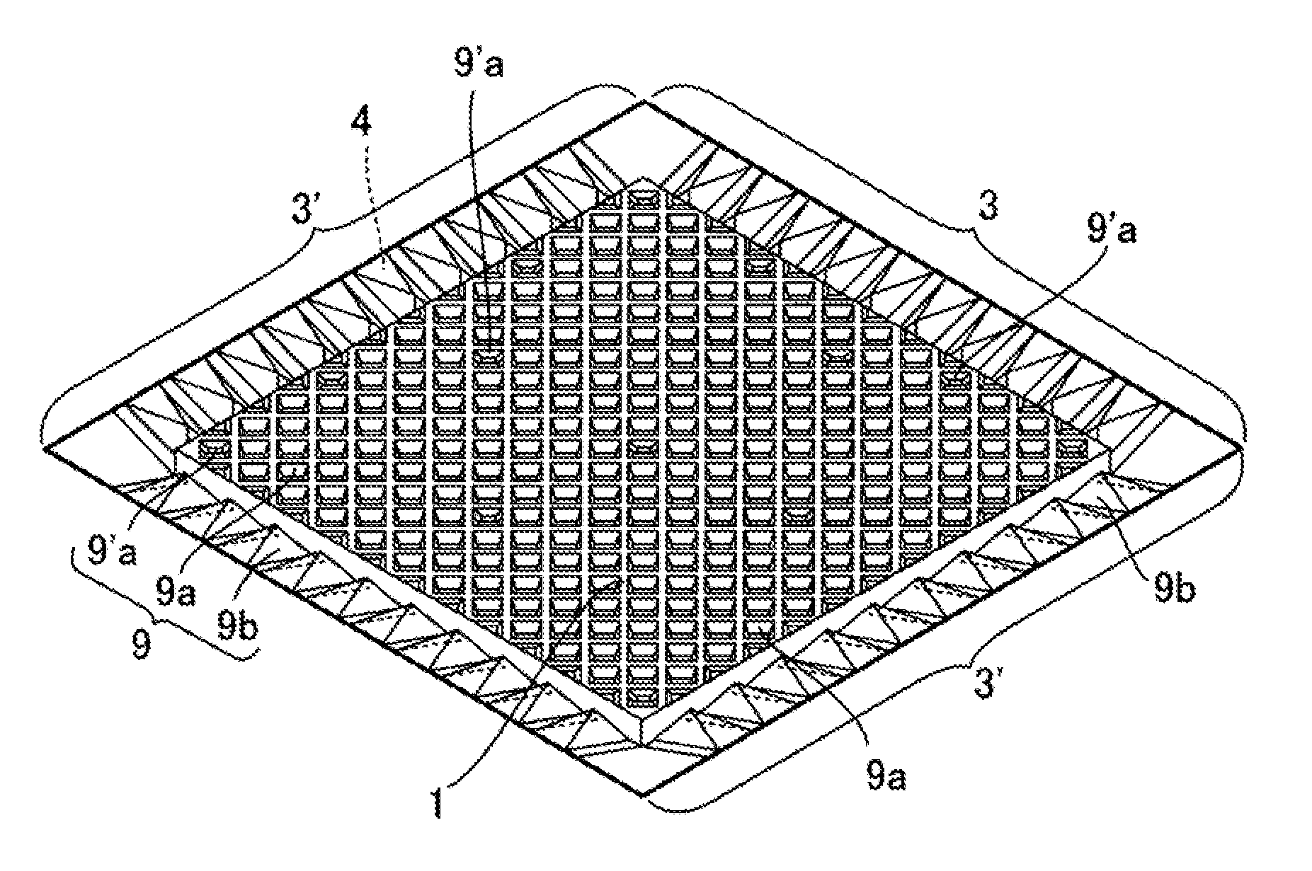
[0098] The configuration characteristic of the present example is a plurality of bottomed lightening portions 9 provided in the placement surface 1 and the ground contact surface 2. Consequently, the weight of the whole cargo handling pallet can be reduced, and nesting during nonuse is enabled.
[0099] Details of the lightening portions 9 are as follows. In the placement surface 1, as illustrated in FIG. 14A, a large number of placement surface central lightening portions 9a depressed in rhombic shapes are formed in the central region so as to be aligned in the longitudinal and lateral directions at equal intervals. Preferably, as illustrated also in FIG. 15, parts of the placement surface central lightening portions 9a are formed as stepped placement surface central lightening portions 9'a, so that half nesting is enabled. In the ground contact surface 2, as illustrated in FIG. 14B, ground contact surface central lightening portions 9c depressed in a grid shape are formed in the central region so as to correspond to the intervals of the adjacent placement surface central lightening portions 9a.
[0100] In the region of the lower surface 3'a of the eaves edge, a plurality of eaves edge lightening portions 9d depressed in rectangular cone shapes having vertexes adjacent to the placement surface 1 is formed at equal intervals. Therefore, the lower surface 3'a of the eaves edge is a discontinuous surface, and the frictional force due to the sliding contact with the upper surface 12a of the distal end of the fork can be reduced. In an upper surface of the eaves edge 3', a plurality of eaves edge lightening portions 9b depressed in shapes conforming to the shaped on the lower surface 3'a of the eaves edge is formed.
[0101] In the present invention, the shapes of the bottomed lightening portions 9 are obviously not limited to the illustrated examples. The shapes of the lightening portions 9 are not particularly limited as long as both the weight reduction and the nesting can be achieved.
[0102] The cargo handling pallet having the plurality of bottomed lightening portions 9 as in the present example is manufactured from a synthetic resin material using a known vacuum/pressure molding technique.
[0103] As described above, according to the cargo handling pallet of the present invention, an improvement in the efficiency of loading cargo into a container or warehouse and an improvement in the work efficiency of the cargo handling work can be achieved in a highly successful manner.
[0104] In the present invention, the placement surface 1, the ground contact surface 2, and the lower surface 3'a of the eaves edge can be discontinuous surfaces including recesses such as holes and grooves as long as the respective functions can be secured.
REFERENCE SIGNS LIST
[0105] 1 Placement surface [0106] 2 Ground contact surface [0107] 3 Edge of placement surface [0108] 3' Eaves edge [0109] 3'a Lower surface of eaves edge [0110] 3'b Lower end of lower surface of eaves edge [0111] 3'c Sliding contact portion [0112] 4 Recess [0113] 5 Side surface [0114] 6 Raised wall [0115] 7 Groove [0116] 8 Penetrating lightening portion [0117] 9 Bottomed lightening portion [0118] 9a Placement surface central lightening portion [0119] 9'a Stepped placement surface central lightening portion [0120] 9b Eaves edge lightening portion [0121] 9c Ground contact surface central lightening portion [0122] 9d Eaves edge lightening portion [0123] 11 Fork [0124] 12 Distal end of fork [0125] 12a Upper surface of distal end [0126] 12b Tip [0127] 13 Roller conveyor [0128] 13A Upper roller [0129] 13B Lower roller [0130] 14 Fork insertion gap [0131] .alpha. Inclination angle of distal end of fork [0132] .beta. Inclination angle of lower surface of eaves edge [0133] G Pallet supporting surface [0134] L1 Depth of recess [0135] L2 Insertion length of distal end of fork [0136] C Cargo
* * * * *
D00000
D00001
D00002
D00003
D00004
D00005
D00006
D00007
D00008
D00009
D00010
D00011
D00012

D00013

D00014

D00015

D00016

D00017
D00018

D00019

D00020

XML
uspto.report is an independent third-party trademark research tool that is not affiliated, endorsed, or sponsored by the United States Patent and Trademark Office (USPTO) or any other governmental organization. The information provided by uspto.report is based on publicly available data at the time of writing and is intended for informational purposes only.
While we strive to provide accurate and up-to-date information, we do not guarantee the accuracy, completeness, reliability, or suitability of the information displayed on this site. The use of this site is at your own risk. Any reliance you place on such information is therefore strictly at your own risk.
All official trademark data, including owner information, should be verified by visiting the official USPTO website at www.uspto.gov. This site is not intended to replace professional legal advice and should not be used as a substitute for consulting with a legal professional who is knowledgeable about trademark law.