A Smoking Article With Liquid-filled Capsule
Ono; Hiroyoshi
U.S. patent application number 16/342358 was filed with the patent office on 2019-08-08 for a smoking article with liquid-filled capsule. This patent application is currently assigned to JT International S.A.. The applicant listed for this patent is JT International S.A.. Invention is credited to Hiroyoshi Ono.
| Application Number | 20190239558 16/342358 |
| Document ID | / |
| Family ID | 57223549 |
| Filed Date | 2019-08-08 |


| United States Patent Application | 20190239558 |
| Kind Code | A1 |
| Ono; Hiroyoshi | August 8, 2019 |
A Smoking Article With Liquid-filled Capsule
Abstract
A smoking article includes a rod element including smokeable material and a filter element having a first end for connection to an end of the rod element and an opposite, second end for insertion into a mouth of a user. A liquid-filled capsule is arranged between the first and second ends of the filter element and the liquid-filled capsule is configured to break upon application of an external force to release the liquid. A tipping wrapper connects the filter element and rod element. The tipping wrapper has a wet tensile strength of at least about 0.15 kN/m. The smoking article is resistant to breakage even after the liquid is released.
| Inventors: | Ono; Hiroyoshi; (Tokyo, JP) | ||||||||||
| Applicant: |
|
||||||||||
|---|---|---|---|---|---|---|---|---|---|---|---|
| Assignee: | JT International S.A. Geneva CH |
||||||||||
| Family ID: | 57223549 | ||||||||||
| Appl. No.: | 16/342358 | ||||||||||
| Filed: | October 30, 2017 | ||||||||||
| PCT Filed: | October 30, 2017 | ||||||||||
| PCT NO: | PCT/EP2017/077818 | ||||||||||
| 371 Date: | April 16, 2019 |
| Current U.S. Class: | 1/1 |
| Current CPC Class: | A24D 3/14 20130101; A24D 1/025 20130101; A24D 3/10 20130101; A24D 3/061 20130101; A24D 3/063 20130101; A24D 1/02 20130101 |
| International Class: | A24D 3/06 20060101 A24D003/06; A24D 1/02 20060101 A24D001/02; A24D 3/14 20060101 A24D003/14; A24D 3/10 20060101 A24D003/10 |
Foreign Application Data
| Date | Code | Application Number |
|---|---|---|
| Oct 31, 2016 | EP | 16196649.4 |
Claims
1. A smoking article, comprising: a rod element comprising smokeable material; a filter element having a first end for connection to an end of the rod element and an opposite, second end for insertion into a mouth of a user; a liquid-filled capsule arranged between the first and second ends of the filter element, the liquid-filled capsule configured to break upon application of an external force to release liquid contained therein; and a tipping wrapper which connects the filter element and the rod element; wherein the tipping wrapper has a wet tensile strength of at least 0.15 kN/m.
2. The smoking article according to claim 1, wherein the tipping wrapper has a dry tensile strength of at least 1 kN/m.
3. The smoking article according to claim 2, wherein the dry tensile strength of the tipping wrapper is no more than 5 kN/m.
4. The smoking article according to claim 1, wherein the wet tensile strength of the tipping wrapper is no more than 0.55 kN/m.
5. The smoking article according to claim 2, wherein a dry tensile strength to wet tensile strength ratio is no more than 15.
6. The smoking article according to claim 1, wherein the tipping wrapper is wrapped about the filter element such that a principal stress direction of the tipping wrapper is substantially parallel to a longitudinal axis of the filter element.
7. The smoking article according to claim 6, wherein the principal stress direction is a cross direction parallel to a longitudinal axis of a roll of tipping wrapper material.
8. The smoking article according to claim 1, wherein the liquid-filled capsule is a directional capsule.
9. The smoking article according to claim 8, wherein the directional capsule comprises a predefined rupture region configured to break upon application of the external force, and the rupture region is directed towards the first end of the filter element.
10. The smoking article according to claim 8, wherein the directional capsule comprises a predefined rupture region configured to break upon application of the external force, and the rupture region is directed towards the second end of the filter element.
11. The smoking article according to claim 1, wherein the filter element further comprises fibrous filtration material between the capsule and the first end of the filter element.
12. The smoking article according to claim 11, wherein the fibrous filtration material extends between the capsule and the first end of the filter element at least 7 mm.
13. The smoking article according to claim 1, wherein the capsule contains a liquid volume of at least 0.05 ml.
14. The smoking article according to claim 1, wherein the tipping wrapper comprises: fibrous material; and a wet-strength additive which acts to increase bonding between fibres of the fibrous material.
15. The smoking article according to claim 14, wherein the fibrous material is paper, and the wet-strength additive is selected from a natural resin, a synthetic resin, or a combination thereof.
Description
TECHNICAL FIELD
[0001] The present invention relates to a smoking article which includes a filter element having a liquid-filled capsule. The characteristics of the smoke produced by the smoking article may be altered by breaking the capsule to release the liquid within the smoking article. The smoking article is configured to withstand breakage, even after wetting of the article following release of the liquid from the capsule.
BACKGROUND
[0002] Smoking articles, such as cigarettes, cigarillos or the like, are popular consumer products that typically have a generally cylindrical rod shaped configuration and include a charge, roll, or column of smokeable material, such as shredded tobacco (e.g. in cut filler form), which is surrounded by a paper wrapper forming a so-called "tobacco rod". A cigarette or cigarillo usually also has a cylindrical filter element aligned in end-to-end relationship with the tobacco rod. The filter element may, for example, comprise a plug of cellulose acetate tow, and the tow is circumscribed by a wrapper material known as "plug wrap". Typically, the filter element is attached to one end of the tobacco rod using a circumscribing wrapping material known as "tipping wrapper". The filter element wrapped by the tipping wrapper is known as a "mouthpiece element".
[0003] In recent years there has been increasing consumer demand for smoking articles providing modified sensory attributes, and particularly for cigarettes incorporating filter elements, which may act as vehicles for adding flavour to mainstream smoke of the cigarettes. Specifically, these smoking articles have included flavour-altering substances in breakable pellets or capsules. During cigarette manufacture, the filter material is formed into a continuous filter rod having such pellets or capsules positioned within that rod; e.g., along a longitudinal axis thereof. The continuous filter rod is then divided or cut at predetermined intervals to form a plurality of filter elements, such that each filter element includes at least one of the capsules. The capsules are then manually broken by the consumer to release a substance into the filter material which acts to alter one or more characteristics of the mainstream smoke during smoking, such as flavour, taste, or TNCO levels (tar, nicotine, CO).
[0004] For this purpose, breakable capsules having a shell, e.g. made of gel, containing the substance to be released have been used. Most recently, such breakable capsules have started to focus on liquid release, especially water release. This can become problematic, however, as the released liquid tends to soak the filter element, including the filter wrapper and the tipping wrapper that joins the filter element to the tobacco rod, which may be weakened. As a result, when a force is applied, for example when the user taps the mouthpiece element to remove the ashes from the lit end of the smoking article, the mouthpiece element may snap off the tobacco rod, especially at the connection between the tobacco rod and filter where a portion of the tipping wrapper overwraps the tobacco rod.
[0005] It is therefore an object of the invention to provide a smoking article with a liquid-filled capsule that can withstand damage under the application of an external force, even after wetting of the smoking article following liquid release. In particular it is desirable to provide a smoking article which mitigates the risk of the mouthpiece element detaching when the consumer taps the mouthpiece element to remove the ashes at the lit end of the smoking article.
SUMMARY OF THE INVENTION
[0006] According to an aspect of the present invention there is provided a smoking article comprising a rod element comprising smokeable material (e.g. a tobacco rod); a filter element having a first end for connection to an end of the rod element and an opposite, second end for insertion into a mouth of a user; a liquid-filled capsule arranged between the first and second ends of the filter element, the liquid-filled capsule configured to break upon application of an external force to release liquid contained therein; and a tipping wrapper which connects the filter element and rod element; wherein the tipping wrapper has a wet tensile strength of at least about 0.15 kN/m.
[0007] The wet tensile strength of the tipping wrapper is selected to ensure that the smoking article can sustain forces experienced during normal use without damage to the components of the smoking article, even after release of the liquid from the capsule. In particular, it has been determined that by using tipping wrapper with a wet tensile strength of 0.15 kN/m or greater, the smoking article is robust to forces associated with use of the smoking article. For example the article may be robust enough to withstand the repetitive forces associated with a user tapping the mouthpiece to remove ash during use. The wet tensile strength may be of at least 0.20 kN/m, for example of at least 0.25 kN/m, such as of at least 0.30 kN/m, or of at least 0.35 kN/m. The wet tensile strength may be of no more than 0.55 kN/m, such as no more than 0.50 kN/m, for example of no more than 0.45 kN/m, or 0.40 kN/m or less.
[0008] The tipping wrapper may have a dry tensile strength of at least 1 kN/m, for example of at least 1.25 kN/m, of at least 1.50 kN/m, such as of at least 1.75 kN/m, or of at least 2 kN/m. By using a tipping wrapper which has a dry tensile strength of 1 kN/m or more (i.e. prior to wetting with the released liquid), the tipping wrapper can withstand pulling forces to which is subject during manufacturing, especially when the tipping wrapper is provided in a reel and, to connect the filter element to the rod element of smokeable material, is pulled from the reel and wrapped about the filter and tobacco at high speed.
[0009] The tipping wrapper may have a dry tensile strength of less than 5 kN/m, for example less than 4 kN/m, such as of less than 3 kN/m.
[0010] The tipping wrapper may have a dry tensile strength to wet tensile strength ratio of no more than 15, for example less than 12, such as less than 9 or less than 6. The tipping wrapper may have a ratio of dry tensile strength to wet tensile strength between 4 and 15, for example of between 5 and 9, such as of between 5 and 7.
[0011] The tensile strengths of the tipping wrapper, wet and dry, are measured along a principal stress direction of the tipping wrapper, which correspond to a set of mutually perpendicular axes where the normal stress tensor is maximised. The wet tensile strength is measured according to ISO 3781:1983, while dry tensile strength is measured according to ISO 1924-2:2008. The principal stress directions in a roll of tipping wrapper material, such as a paper roll of tipping wrapper (i.e. a roll of tipping paper), are called machine direction (MD), cross direction (CD), and z-direction (ZD), and have been represented in FIG. 1. Both the machine direction and the cross direction are contained in the plane of the tipping wrapper material; the machine direction being the direction in which the material is pulled from the roll, and the cross direction parallel to the longitudinal axis of the roll and oriented in the winding direction of the roll. The z-direction is perpendicular to the plane of the tipping wrapper material and, therefore, to the other two principal directions. When the roll of tipping wrapper material is wound, the z-direction points radially towards the longitudinal axis of the roll. Preferably, wet and dry tensile strength measurements are conducted along the machine direction.
[0012] The tipping wrapper is preferably wrapped about the filter element with a principal stress direction substantially parallel to a longitudinal axis of the filter element. Preferably, this principal stress direction is the cross direction, as, generally, the machine direction has a higher tensile strength than the cross direction, and this eases manufacturing at high speed, as explained above.
[0013] The liquid-filled capsule may be an isotropic capsule configured to break upon the application of a predetermined compressive force. The liquid-filled capsule may break to release the liquid uniformly or in one or more directions. The liquid-filled capsule may be a spherical capsule.
[0014] The liquid-filled capsule may be a directional capsule, a directional capsule being a capsule containing a volume of liquid that is adapted to direct liquid release into a particular desired direction or towards a particular desired region.
[0015] The directional capsule may be configured to break at a predetermined rupture region upon application of the external force to release the liquid substantially from the rupture region. The use of a tipping wrapper having a wet tensile strength of 0.15 kN/m or greater is particularly important when a directional capsule is used because released liquid is directed into a particular area of the article. By providing a relatively high tensile strength in the tipping wrapper in this area the smoking article may have an improved robustness against breakage.
[0016] The rupture region of the capsule may be arranged to release the liquid in an axial direction, such as a longitudinal axis of the filter element.
[0017] Some breakable capsules have an isotropic resistance to break, which may result in a difficulty in determining the specific rupture location of the capsule, and accordingly the region of the filter element into which the contained substance is released. With a directional capsule liquid is released into a predetermined portion of the article, which can be strengthened within the defined tipping wrapper, thereby mitigating the effects of damage. Certain directional capsules can eject liquid in a jet, the force of which may depend on the crushing force applied by the consumer. Thus, liquid may be propelled away from the directional capsule with a degree of force, which may extend the wetting of the smoking article further towards the tobacco end than may be typical with non-directional capsules. This only increases the importance of providing the tipping wrapper with a relatively high wet tensile strength, which is greater than 0.15 kN/m.
[0018] The use of a directional capsule may also influence the position in the smoking article in which the liquid is released which can have an impact on the changes in smoke characteristics, such as flavour, provided by the liquid. Therefore control over the location in which the liquid is released may also be important in order to provide better control on the effects of the liquid on the inhaled smoke.
[0019] The rupture region may be directed towards the first end of the filter element. Thus, liquid may be deposited close to the connection end of the rod element. However, as described, this area may be particularly susceptible to weakening via the absorption of released liquid and therefore this may increase the likelihood of rod detachment. The use of the tipping wrapper with a wet tensile strength of more than 0.15 kN/m in this region can help to ensure that the rod is not detached in normal use.
[0020] The rupture region may be directed towards the second end of the filter element. In this way, the liquid may be directed away from the area of the article most susceptible to weakening after wetting.
[0021] The filter element may further comprise fibrous filtration material between the capsule and the first end of the filter element. By providing fibrous filtration material upstream of the directional capsule, the effect of the released liquid on the characteristics of the mainstream smoke is prolonged in time. The fibrous filtration material may be arranged immediately adjacent the directional capsule, for example immediately adjacent the rupture region of the directional capsule. By arranging the fibrous filtration material immediately adjacent the directional capsule, progression of liquid towards the weakest region of the smoking article, the region where the tipping wrapper solely overlies the rod element of smokeable material (connection region), can be controlled. The fibrous filtration material may extend at least 7 mm, for example 9 mm, between the directional capsule and the first end of the filter element. By providing this amount of fibrous filtration material immediately upstream of the directional capsule liquid leakage is mitigated and the effect of the released liquid on the characteristics of the mainstream smoke is prolonged in time.
[0022] In one arrangement the capsule may contain a liquid volume of at least 0.05 ml. In another arrangement the capsule may contain a volume of at least 0.07 ml or at least 0.08 ml. This volume of liquid may be significantly greater than known devices. The use of a high volume capsule only increases problems that may be experienced in the smoking article due to wetting. Therefore, this provides a further advantage for the use of a relatively high wet tensile strength tipping wrapper, which is greater than 0.15 kN/m.
[0023] In a preferred arrangement the volume of liquid in the directional capsule may be no more than 0.15 ml, for example no more than 0.12 ml, or no more than 0.10 ml. By providing such volume of liquid, liquid leakage is mitigated further.
[0024] The tipping wrapper may comprise fibrous material and a wet-strength additive which acts to increase the bonding between the fibres of the fibrous material. The additive may be added during manufacture, such as during the curing process, so as to be embedded in the fibres. The increased bonding between fibres may be facilitated by cross-linking of the molecules of the additive. By adding a wet-strength additive to increase the bonding between the fibres, the wet tensile strength of the tipping wrapper may be increased. In some arrangements the fibrous material may be paper, and the wet-strength additive may be a polymer. The wet-strength additive may be selected from a natural resin, a synthetic resin, or a combination of them.
[0025] The filter element may further comprise a filter wrapper at least partly extending between the first and second ends of the filter element. The provision of such a filter wrapper may aid to retain the liquid within the filter element and, thus, mitigate still further leakage, as well further prolong in time the effect on the characteristics of the mainstream smoke. By providing such filter wrapper, the weakest region of the smoking article after liquid release is further localised at the connection between the filter and rod element provided by the tipping wrapper and accordingly results in further strengthening the smoking article against the weakening effects of the released liquid.
[0026] The filter element may comprise at least two filter segments combined by the filter wrapper. In this way, the capsule may be provided within one such filter segment and filtration material may be provided in one or more further filter segments, which may simplify manufacture of the smoking article.
BRIEF DESCRIPTION OF THE DRAWINGS
[0027] Embodiments of the invention will now be described, by way of example only, with reference to the accompanying drawings, in which:
[0028] FIG. 1 shows the principal stress directions in a roll of tipping wrapper material;
[0029] FIG. 2 is a side cross-sectional view of a filter element for use in a smoking article in an embodiment of the present invention;
[0030] FIG. 3 is a side view of a smoking article in an embodiment of the present invention; and
[0031] FIG. 4 is an isometric view of a smoking article in an embodiment of the present invention showing filter and tipping wrappers in an unwrapped condition.
DETAILED DESCRIPTION
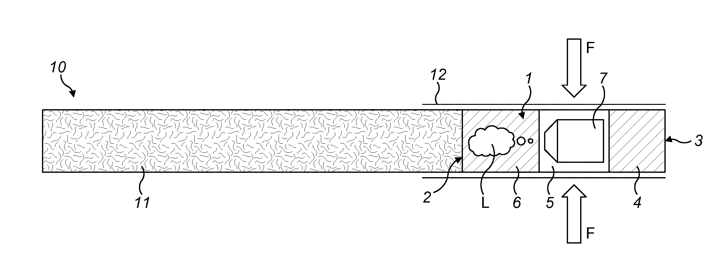
[0032] FIG. 3 is a schematic side view of a smoking article 10 in an embodiment of the present invention. The smoking article 10 comprises a rod element 11, containing a smokeable material, connected to a filter element 1. The filter element has a first end 2 for connection to an end of the rod element 11 and a second end 3 through which smoke is inhaled into the mouth of a user. A liquid-filled capsule 7 is provided between the first 2 and second 3 ends of the filter element 1. The liquid filled capsule 7 is configured to break upon application of a force F to release a liquid L. The rod 11 and filter 1 elements are connected in a linearly aligned relationship with a tipping wrapper 12 which extends over at least the connected ends. The tipping wrapper 12 has a wet tensile strength of at least 0.15 kN/m, preferably of at least 0.20 kN/m.
[0033] The tipping wrapper 12 may be made of fibrous material such as paper that comprises a wet-strength additive. The wet-strength additive may include at least one of a natural polymer, such as starch or carboxymethylcellulose (CMC), or a synthetic resin, such as polyacrylamide (PAM), glyoxalated polyacrylamide (GPAM), or polyamide-epichlorohydrin (PAE). These resins typically work during the curing process of the paper, when the functional groups on the polymer react with cellulose fiber to form a covalent bond. The polymer molecules cross-link, forming a network in the cellulose web that provides strength when the paper becomes wet. Wet-strength additives can also reinforce existing fibre-to-fibre bonds, which further enhance the strength of the paper. The wet-strength additive may be applied in a quantity sufficient to saturate the cellulose fibres.
[0034] The rod element 11 is a tobacco rod and the smokeable material comprises tobacco. For example, the smokeable material may be cut filler tobacco. The cut filler tobacco may comprise types of tobacco such as Virginia, Burley, Oriental and Semi Oriental. The tobacco cut filler may comprise a blend of two or more different types of tobacco; e.g. of the above-mentioned types of tobacco. Alternatively, the tobacco cut filler may comprise a single one of the above-mentioned types of tobacco. The tobacco cut filler may comprise tobaccos that are, for example, air, sun or flue-cured. Alternatively or in addition, the tobacco cut filler may have undergone treatment, for example, to reduce tobacco-specific nitrosamines (TSNA). Besides tobacco leaf, the tobacco cut filler may include other ingredients typically found in tobacco cut filler such as, for example, expanded tobacco, homogenized tobacco (e.g. reconstituted tobacco, cast tobacco, or extruded tobacco), tobacco stem (e.g. expanded or improved stem), tobacco fines, and any combinations thereof. Flavours and casings comprising one or more humectants, flavourants, sugars or combinations thereof may also be applied to the tobacco cut filler in a known manner.
[0035] The rod element 11 is substantially cylindrical in shape, with smokeable material circumscribed by an outer wrapper of smokeable cigarette paper. The filter element 1 is also cylindrical in shape with a cross-section substantially matching that of the rod element 11. The filter element 1 contains filter plugs 4, 6 comprising filtration material to filter the mainstream smoke as it passes between the first 2 and second ends 3. Examples of suitable filtration material include cellulose acetate, paper and combinations thereof. The filter element may have at least one filter segment comprised of a fibrous filtration material, and optionally multiple segments comprised of a fibrous filtration material, typically a cellulosic filtration material, such as cellulose acetate tow.
[0036] The filter element 1 itself typically has a length in the range of about 5 mm to 40 mm, preferably in the range of about 15 mm to about 30 mm.
[0037] The liquid-filled capsule 7 is positioned within the filter element 1 between the first 2 and second 3 ends. The capsule 7 comprises an outer shell containing a liquid L, which may include one or more flavourings. The shell of the capsule 7 is configured to break under a user-applied force F to release the liquid L. The shell may be made from a resiliently deformable material, such as a polymer material. The liquid in the capsule may comprise purified water or a water-based liquid which contains a dissolved or suspended substance, such as a flavouring substance.
[0038] The capsule 7 is configured such that a force applied to the outer side of the filter with the user's fingers, for example in an inward radial direction as shown in FIG. 3, is sufficient to break the capsule 7 and release a substantial amount of the liquid L contained therein. The liquid-filled capsule 7 depicted in FIG. 3 is a directional capsule 7 configured to release the liquid in a predetermined direction, as will be described in further detail with reference to FIG. 2.
[0039] In the presently described embodiment the capsule 7 has a partially trapezoidal shape. In other embodiments the capsule 7 may be elongate. Alternatively, the capsule 7 may be substantially spherical, or ovoidal. The capsule 7 may be a seamless shell. Alternatively, the capsule 7 may be an open-ended shell, which is closed and sealed with a cap. The shell may have a side wall or lateral wall that extends from an end wall to an open end and thus surrounds or defines a cavity in the shell. The lateral wall may end in a rim at the open end to facilitate application of the cap. The lateral wall may be generally cylindrical or may be faceted. The side or lateral wall may taper or narrow from the open end towards the end wall. The cap is typically formed and cut from a section or an expanse of sheet material, such as a laminated plastic sheet material.
[0040] The liquid capsule 7 may contain a liquid volume of at least 0.05 ml. By providing this volume of liquid, the quantity of liquid released with one compression is sufficient to produce an effect on the characteristics of the mainstream smoke. This is a relatively high liquid volume in comparison to liquid capsules that have been used previously. The breakage of the liquid capsule 7 therefore causes significant wetting within the smoking article 1, which can extend within the filter element 1 and also within part of the rod element 11. The tipping wrapper 12 can also become wet. In the presently described embodiment the tipping wrapper 12 has a wet tensile strength of at least 0.15 kN/m. It has been determined that this property of the tipping wrapper 12 provides sufficient robustness under normal use to prevent detachment of the rod element 11 from the filter element 1 even after the liquid L has been released.
[0041] The first, connection end 2 of the filter element abuts an end of the rod element 11 and the connection is secured via the circumferential wrapping of the tipping wrapper 12 which surrounds at least the join between the rod 11 and filter 1 elements. The tipping wrapper 12 extends over the connection in both opposing axial directions and is attached to the outer surface of the rod 11 and filter 1 elements, for example via an adhesive. The length that the attached tipping wrapper 12 extends either side of the connection may be varied with a greater extension enhancing the strength of the connection between the filter 1 and rod 11 but also having implications on the characteristics of the inhaled smoke if it extends too far along the tobacco rod such that it is burned during use.
[0042] Typically, the tipping wrapper 12 is generally rectangular and is wrapped cylindrically around at least part of the rod element 11 of smokeable material and at least part of the filter element 1, as can be seen in FIG. 4. The tipping wrapper 12 is wrapped around and thereby encompasses or envelops at least part of the filter element 1 so that the tipping wrapper 12 physically and mechanically attaches or connects the filter element 1 to the rod element 11 of smokeable material. In this way, the tipping wrapper 12 will typically encompass or circumscribe the filter element 1 and an adjacent end portion of the rod element 11 of smokeable material. Thus, the portion of the rod element 11 of smokeable material encompassed or circumscribed by the tipping wrapper 12 is typically in the range of 1 mm to 16 mm in length, for example in the range of 2 mm to 12 mm in length. As used herein, the term "length" denotes the dimension in the axial or longitudinal direction of the smoking article 10.
[0043] The tipping wrapper 12 may include a bonding region in which an adhesive is applied. That is, the tipping wrapper 12 is typically bonded in a region in which the tipping wrapper 12 overlaps with itself when wrapped around the filter element 1 and at least part of the rod element 11 of smokeable material. The bonding region is preferably elongate and extends in a longitudinal direction of the smoking article 10; for example, along an edge portion of the tipping wrapper 12.
[0044] As discussed, the tipping wrapper 12 has a wet tensile strength of at least 0.15 kN/m. In some embodiments the tipping wrapper 12 has a wet tensile strength of at least 0.25 kN/m, for example of about 0.35 kN/m. The tipping wrapper 12 has a wet tensile strength of less than about 0.55 kN/m.
[0045] The tipping wrapper 12 has a dry tensile strength of at least about 1 kN/m, for example of at least about 1.25 kN/m, such as of at least about 1.5 kN/m. The tipping wrapper 12 has a dry tensile strength of less than about 5 kN/m, for example of no more than 3 kN/m.
[0046] The tipping wrapper 12 has a dry to wet tensile strength ratio of no more than 15, for example 12 or less, 9 or less or, most preferably 6 or less. Tests have indicated that a range of 5 to 7 for the dry to wet tensile strength ratio is achievable and provides a beneficial effect in maintaining the strength of the tipping wrapper as it transitions from a dry to wet state.
[0047] In use, a force is applied by the user to the outer surface of the filter element 1 in a direction indicated by arrows F in order to break the capsule and release the liquid L. This force is typically provided by the opposing pressure of the fingers of the user in a direction perpendicular to the elongate axis of the smoking article 10 as indicated by arrows F. Under this pressure the filter element 1 deforms inwardly, producing a corresponding force on the capsule 7 such that the shell deforms with the increasing internal pressure resulting in rupture and expulsion of the liquid L.
[0048] The liquid L is expelled from the capsule 7 and disperses within the filtration material 6, 4. A portion of the released liquid L may also travel towards the tipping wrapper 12 and may reach and be absorbed by the tipping wrapper 12. In embodiments where the filter element 1 is wrapped by a filter wrapper 8 (FIG. 4), typically when the filter element 1 comprises more than one segment, the tipping wrapper 12 is attached to the filter element 1 by applying adhesive onto the filter wrapper 8. However, application of adhesive is generally only along a line parallel to the longitudinal axis of the filter element 1 and there is a gap between the filter wrapper 8 and the tipping wrapper 12 through which the released liquid L can rapidly advance by capillary action, once it soaks the filter wrapper 8 and leaks through it and into this region. When the liquid is released towards the first filter end 2, or tobacco end, the liquid advances towards the tobacco rod 11 and may reach and be absorbed by the region of tipping wrapper 12 that connects the tobacco rod 11 to the filter element 1, which is the weakest region of the smoking article 10.
[0049] The smoking article 10 is ignited at the opposite end of the tobacco rod 11 to the filter 1 and the resultant smoke travels through the tobacco rod 11 and filter element 1, passing through the dispersed liquid L where it affects the characteristics of the mainstream smoke before being inhaled by the user at the second end of the filter 3. In normal use, the user typically taps the mouthpiece 1 to dislodge spent ash. The wet tensile strength of the tipping wrapper 12 is selected to provide sufficient strength such that the smoking article may resist damage that may otherwise occur, such as detaching of the rod 11 from the filter 1, even if liquid reaches and is absorbed by the tipping wrapper 12 at the region where it connects the tobacco rod 11 to the filter element 1.
[0050] The liquid-filled capsule 7 is a directional capsule which is configured to release liquid L in a predetermined direction via the provision of a known rupture region P. For example, the shell of the capsule 7 is configured such that it has a weak point or region P which gives way preferentially on the application of a force F such that the contained liquid L is ejected from this known point or region. The weakened region may comprise one or more lines of weakness. Alternatively, the weakened region may comprise one or more stress concentrator elements. A combination of lines of weakness and stress concentrator elements would also be possible to form the weakened region.
[0051] The rupture region of the directional capsule 7 may be arranged such that the liquid L is released in an axial direction, such as a longitudinal axis of the filter element 1, into an adjacent region of the filtration material. The shell of the directional capsule 7 and the rupture region P may be configured such that the user applied force causes expulsion or jetting of the liquid L in the predetermined direction. The jetting of the liquid L may increase the speed with which liquid L reaches the tipping wrapper 12. The jetting may also increase the amount of liquid L which reaches the tipping wrapper 12, especially a localised region of the tipping wrapper 12, such as a tobacco to filter connection region. These factors increase the importance of having a tipping wrapper 12 with a high wet tensile strength, which is greater than 0.15 kN/m.
[0052] In the presently described embodiment, the rupture region P of the directional capsule 7 faces the first, connection end 2 of the filter element 1. In this way, the released liquid L is dispersed adjacent to the first end 2 of the filter element 1. Although this area of the smoking article 10, near the connection point of the rod 11 and filter 1 elements, is known to be a weak point (particularly following wetting), the strengthening provided by the defined tipping wrapper 12 is such that the risk of snapping is mitigated. The desired effects on the characteristics of the mainstream smoke are therefore obtained without increased risk of damage to the smoking article 10.
[0053] The distance D between the rupture region P of the capsule 7 and the first end of the filter element 1 may also be adjusted such that the ejected liquid L is positioned at an optimum location. Testing has shown that a distance of at least 7 mm, preferably at least 9 mm, provides an optimum dispersion of the liquid L without projecting the expelled liquid too far into the tobacco rod 11.
[0054] The filter element 1 may further comprise a plurality of filter segments arranged in series along a longitudinal axis of the filter element 1. In the example of FIGS. 2 and 3, the filter element 1 comprises three filter segments 4, 5, 6. The directional capsule 7 is provided in the central filter segment 5, with a filter segment containing a filter plug positioned on both the upstream 6 and downstream 4 sides. The filter segments are connected by a filter wrapper 8 (shown in FIG. 4), which is circumferentially wrapped around the filter segments 4, 5, 6 to secure them together.
[0055] In other embodiments one or more filter segments may be individually wrapped and some or all of the filter segments may be combined by a combiner filter wrapper 8.
[0056] In some embodiments at least one filter segment may contain a particulate material, such as a sorbent or flavouring. The particulate material may be embedded in fibrous filtration material or contained in a cavity. The particulate material may be arranged between the rupture region P of the directional capsule 7 and the first end 2 of the filter element 1, or between the second end 3 of the filter element 3 and the directional capsule 7. Selection will depend on the desired effect on the characteristics of the mainstream smoke through the filter element 1.
[0057] In other embodiments the filter element 1 comprises a single filter segment within which the liquid capsule 7 is arranged.
[0058] Although in the embodiment of FIGS. 2 and 3, the directional capsule 7 is arranged such that the rupture region P is located closer to the first end 2 of the filter element 1, in alternative embodiments the directional capsule 7 may be arranged in the filter element 1 with the rupture region P located closer to the second end 3 of the filter element than to the first end 2 of the filter element 1.
[0059] Although in the described embodiment, one capsule 7 is provided in the filter element 1, in alternative embodiments the filter element 1 may comprise more than one capsule 7, for example one or more directional capsules 7 and one or more non-directional capsules. Where one or more directional capsules 7 are provided, all of the directional capsules 7 may be oriented in the same direction; alternatively, one or more directional capsules may be oriented in a first direction (with their respective rupture point P pointing towards the end 2 for connection to the rod element 11 of smokeable material, i.e. the first end 2 of the filter element 1) and one or more capsules 7 may be oriented in a second direction (with their respective rupture region P pointing towards the end for insertion into the mouth of the user, i.e. the second end 3 of the filter element 1).
[0060] The above described embodiments refer to a directional capsule 7. In other embodiments a non-directional capsule may be used. The capsule may for example be an isotropic capsule such as a conventional spherical capsule.
[0061] FIG. 4 shows a preferred way of connecting the tobacco rod 11 to the filter element 1 with the tipping wrapper 12. The tipping wrapper 12 is pulled in the machine direction (MD) from a reel of tipping wrapper material (FIG. 1) and wrapped about the filter element 1 such that the cross direction (CD) of the tipping wrapper material is substantially parallel to the longitudinal axis of the filter element 1. As a result, the tipping wrapper 12 is wrapped about the filter element 1 and the tobacco rod 11 so that the cross direction (CD) is substantially parallel to the longitudinal axis of the filter element 1.
[0062] Alternatively, the tipping wrapper 12 may be wrapped about the filter element 1 such that the machine direction (MD) of the tipping wrapper material is substantially parallel to the longitudinal axis of the filter element 1. As a result, the tipping wrapper 12 is wrapped about the filter element 1 and the tobacco rod 11 so that the machine direction (MD) is substantially parallel to the longitudinal axis of the filter element 1.
* * * * *
D00000
D00001
D00002
XML
uspto.report is an independent third-party trademark research tool that is not affiliated, endorsed, or sponsored by the United States Patent and Trademark Office (USPTO) or any other governmental organization. The information provided by uspto.report is based on publicly available data at the time of writing and is intended for informational purposes only.
While we strive to provide accurate and up-to-date information, we do not guarantee the accuracy, completeness, reliability, or suitability of the information displayed on this site. The use of this site is at your own risk. Any reliance you place on such information is therefore strictly at your own risk.
All official trademark data, including owner information, should be verified by visiting the official USPTO website at www.uspto.gov. This site is not intended to replace professional legal advice and should not be used as a substitute for consulting with a legal professional who is knowledgeable about trademark law.