Management Of Heat Conduction Using Phonononic Regions Formed With Void Nanostructures
McConkey; Joshua S.
U.S. patent application number 16/092485 was filed with the patent office on 2019-04-25 for management of heat conduction using phonononic regions formed with void nanostructures. This patent application is currently assigned to Siemens Aktiengesellschaft. The applicant listed for this patent is Siemens Aktiengesellschaft. Invention is credited to Joshua S. McConkey.
| Application Number | 20190120080 16/092485 |
| Document ID | / |
| Family ID | 55802517 |
| Filed Date | 2019-04-25 |

| United States Patent Application | 20190120080 |
| Kind Code | A1 |
| McConkey; Joshua S. | April 25, 2019 |
MANAGEMENT OF HEAT CONDUCTION USING PHONONONIC REGIONS FORMED WITH VOID NANOSTRUCTURES
Abstract
A gas turbine engine component formed of material having phononic regions. The phononic regions are formed of void nanostructures. The phononic regions modify the behavior of the phonons and manage heat conduction.
| Inventors: | McConkey; Joshua S.; (Orlando, FL) | ||||||||||
| Applicant: |
|
||||||||||
|---|---|---|---|---|---|---|---|---|---|---|---|
| Assignee: | ; Siemens
Aktiengesellschaft Munchen DE |
||||||||||
| Family ID: | 55802517 | ||||||||||
| Appl. No.: | 16/092485 | ||||||||||
| Filed: | April 12, 2016 | ||||||||||
| PCT Filed: | April 12, 2016 | ||||||||||
| PCT NO: | PCT/US2016/027077 | ||||||||||
| 371 Date: | October 10, 2018 |
| Current U.S. Class: | 1/1 |
| Current CPC Class: | Y02T 50/60 20130101; F05D 2300/6012 20130101; F05D 2300/5024 20130101; F23M 2900/05004 20130101; F05D 2300/6032 20130101; Y02T 50/675 20130101; Y02T 50/672 20130101; F05D 2300/6034 20130101; F05D 2250/191 20130101; F05D 2260/204 20130101; F01D 25/12 20130101; C23C 30/00 20130101; F01D 5/28 20130101; F23R 3/005 20130101; Y02T 50/6765 20180501; F05D 2260/221 20130101; F23R 3/002 20130101 |
| International Class: | F01D 25/12 20060101 F01D025/12 |
Claims
1-18. (canceled)
19. A gas turbine engine component comprising: a first region of a first material; and a phononic region comprising void nanostrcutures within the first material; wherein phononic transmittal of phonons through the first material forms a first phononic wave having the phonons; and wherein, upon transmittal of the first phononic wave to the phononic region, the phononic region is configured to modify a behavior of the phonons of the first phononic wave.
20. The gas turbine engine component of claim 19, wherein the first phononic wave has a first property, wherein the phononic region is configured to the behavior of the phonons of the first phononic wave to form a second phononic wave having a second property different than the first property of the first phononic wave.
21. The gas turbine engine component of claim 20, wherein the first property and the second property are frequency.
22. The gas turbine engine component of claim 20, wherein the first property and the second property are modes of propagation.
23. The gas turbine engine component of claim 19, wherein the phononic region modifies the behavior of the phonons of the first phononic wave so that the phonons of the first phononic wave change direction of propagation.
24. The gas turbine engine component of claim 19, wherein the phononic region modifies the behavior of the phonons of the first phononic wave so that the phonons of the first phononic wave scatter.
25. The gas turbine engine component of claim 19, wherein the phononic region modifies the behavior of the phonons of the first phononic wave so that the phonons of the first phononic wave are reflected, refracted, or dissipated.
26. The gas turbine engine component of claim 19, wherein the phononic region is selected from the group consisting of a void sphere, a nanovoid divot, and void channel.
27. The gas turbine engine component of claim 26, wherein the void nanostructures comprise void spheres having a diameter of from 5-1000 nm.
28. The gas turbine component of claim 27, wherein the void spheres are formed in rows within the first material.
29. The gas turbine engine component of claim 26, wherein the void nanostructures comprises void columns having a diameter of from 5-1000 nm.
30. A method for controlling heat conduction in a gas turbine engine comprising: forming a phononic region within a first region of a first material of a gas turbine engine component, wherein the phononic region comprises void nanostructures; transmitting phonons through the first material to form a first phononic wave having the phonons; transmitting the first phononic wave to the phononic region, and modifying a behavior of the phonons of the first phononic wave in the phononic region to manage heat conduction.
31. The method of claim 30, wherein the first phononic wave has a first property, wherein the phononic region modifies the behavior of the phonons of the first phononic wave to form a second phononic wave having a second property different than the first property of the first phononic wave.
32. The method of claim 30, wherein the first property and the second property are frequency or modes of propagation.
33. The method of claim 30, wherein the modified behavior of the phonons of the first phononic wave is a changed direction of propagation of the phonons of the first phononic wave.
34. The method of claim 30, wherein the modified behavior of the phonons of the first phononic wave is at least one of scattering, reflection, refraction, or dissipation of the phonons of the first phononic wave.
35. The method of claim 30, wherein the phononic region is selected from the group consisting of a void sphere, a nanovoid divot, and void channel.
36. The method of claim 35, wherein the void nanostructures comprise void spheres having a diameter of from 5-1000 nm.
37. The method of claim 36, wherein the void spheres are formed in rows within the first material.
38. The method of claim 35, wherein the void nanostructures comprise void columns having a diameter of from 5-1000 nm.
Description
BACKGROUND
[0001] Disclosed embodiments are primarily related to gas turbine engines and, more particularly to phonon management in gas turbine engines. However, the disclosed embodiments may also be used in other heat impacted devices, structures or environments.
2. Description of the Related Art
[0002] Gas turbines engines comprise a casing or cylinder for housing a compressor section, a combustion section, and a turbine section. A supply of air is compressed in the compressor section and directed into the combustion section. The compressed air enters the combustion inlet and is mixed with fuel. The air/fuel mixture is then combusted to produce high temperature and high pressure gas. This working gas then travels past the combustor transition and into the turbine section of the turbine.
[0003] Generally, the turbine section comprises rows of vanes which direct the working gas to the airfoil portions of the turbine blades. The working gas travels through the turbine section, causing the turbine blades to rotate, thereby turning a rotor in power generation applications or directing the working gas through a nozzle in propulsion applications. A high efficiency of a combustion turbine is achieved by heating the gas flowing through the combustion section to as high a temperature as is practical. The hot gas, however, may degrade the various metal turbine components, such as the combustor, transition ducts, vanes, ring segments and turbine blades that it passes when flowing through the turbine.
[0004] For this reason, strategies have been developed to protect turbine components from extreme temperatures such as the development and selection of high temperature materials adapted to withstand these extreme temperatures and cooling strategies to keep the components adequately cooled during operation.
[0005] Some of the components used in the gas turbine engines are metallic and therefore have very high heat conductivity. Insulating materials, such as ceramic may also be used for heat management, but their properties sometimes prevent them from solely being used as components. Therefore, providing heat management to improve the efficiency and life span of components and the gas turbine engines is further needed. Of course, the heat management techniques and inventions described herein are not limited to use in context of gas turbine engines, but are also applicable to other heat impacted devices, structures or environments.
SUMMARY
[0006] Briefly described, aspects of the present disclosure relate to materials and structures for managing heat conduction in components. For example gas turbine engines, kilns, smelting operations and high temperature auxiliary equipment.
[0007] An aspect of the disclosure may be a gas turbine engine having a gas turbine engine component having a first material, wherein phononic transmittal through the first material forms a first phononic wave; and a phononic region located within the gas turbine engine component, wherein the phononic region is a void nanostructure formed in the first material, wherein phononic transmittal through the void nanostructure modifies behavior of the phonons of the first phononic wave thereby managing heat conduction.
[0008] Another aspect of the present disclosure may be a method for managing heat conduction in a gas turbine engine comprising forming a phononic region by forming a void nanostructure in a first material of a gas turbine engine component, wherein phononic transmittal through the first material forms a first phononic wave; and modifying behavior of phonons transmitted through the first material when the phonons are transmitted to the void forming the phononic region thereby managing heat conduction.
BRIEF DESCRIPTION OF THE DRAWINGS
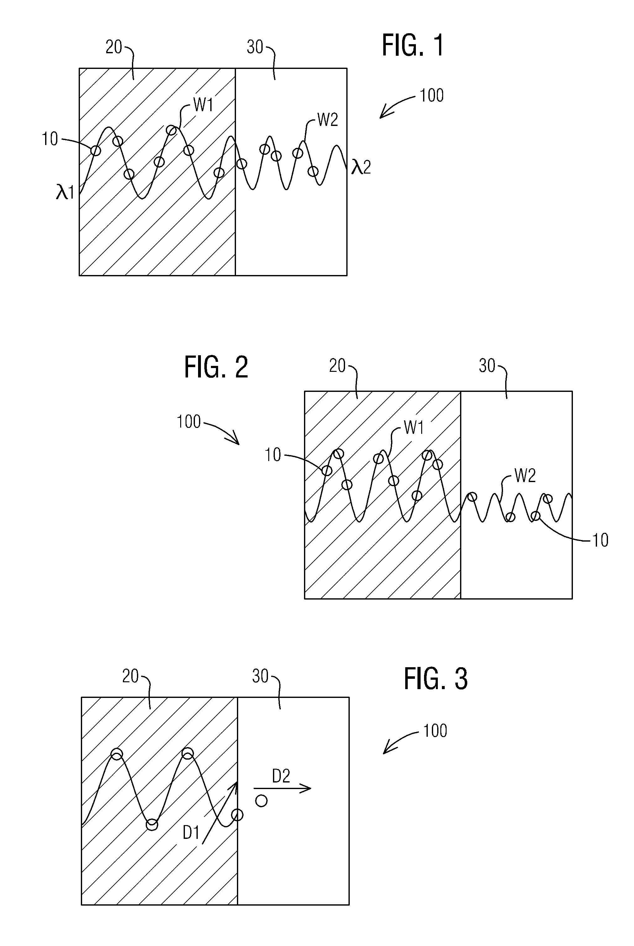
[0009] FIG. 1 is a diagram of phonons interacting with a phononic region where a wave property is modified.
[0010] FIG. 2 is a diagram of phonons interacting with a phononic region where the mode of propagation is altered.
[0011] FIG. 3 is a diagram of phonons interacting with a phononic region where the movement direction of the phonon is changed.
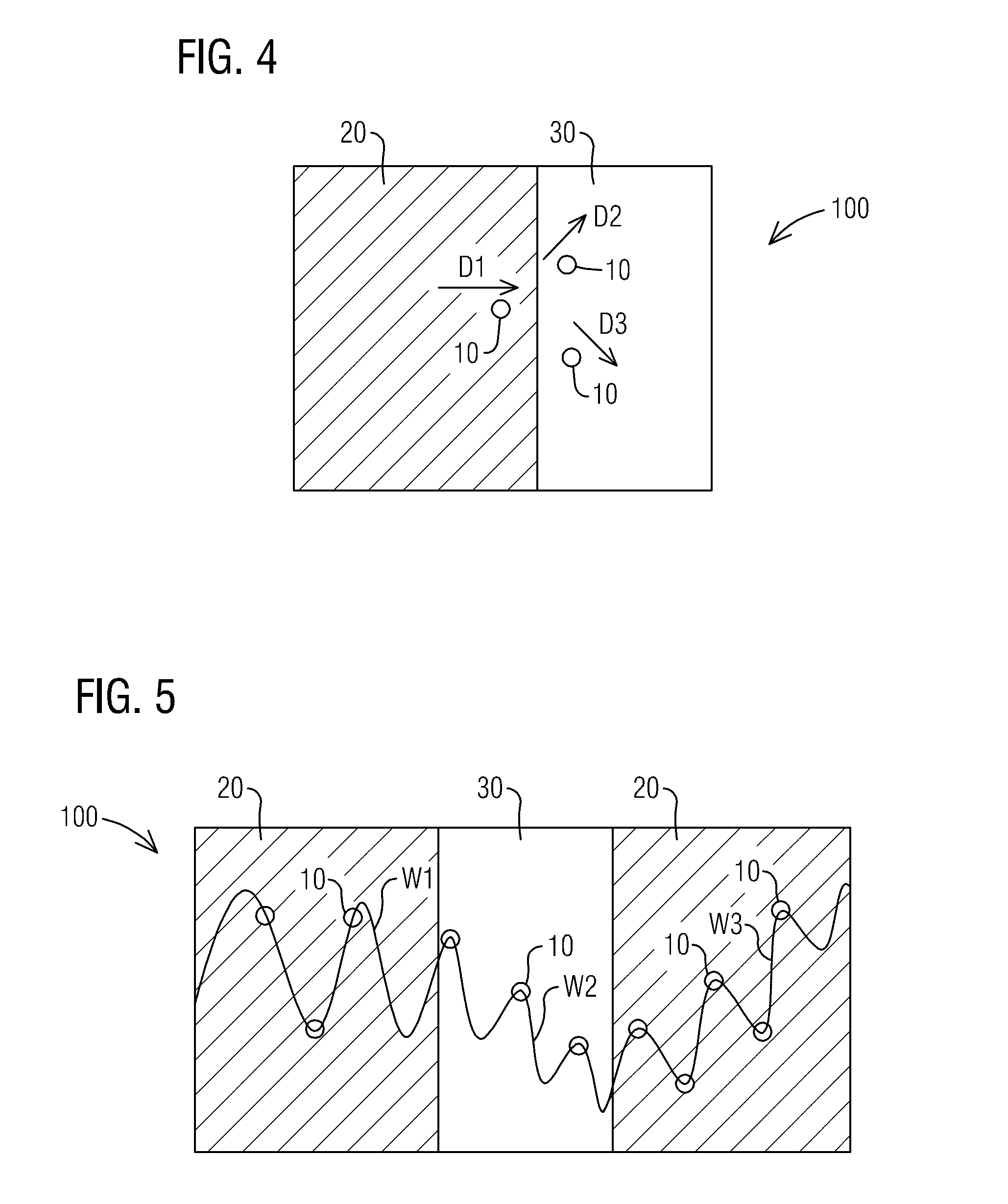
[0012] FIG. 4 is a diagram of phonons interacting with a phononic region where the phonons are scattered.
[0013] FIG. 5 is a diagram of phonons interacting with a phononic region where waves are refracted.
[0014] FIG. 6 is a diagram of phonons interacting with a phononic region where the phonons are dissipated.
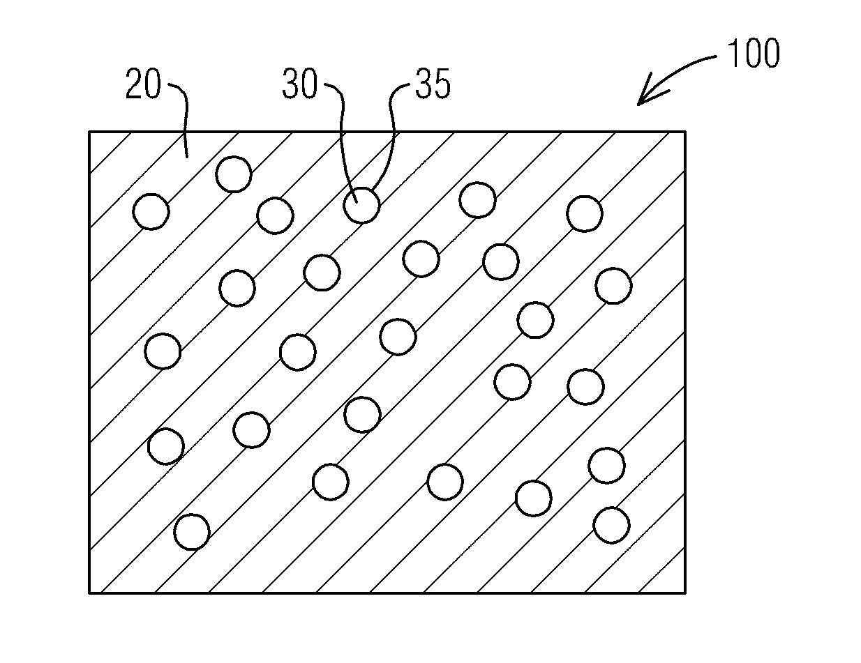
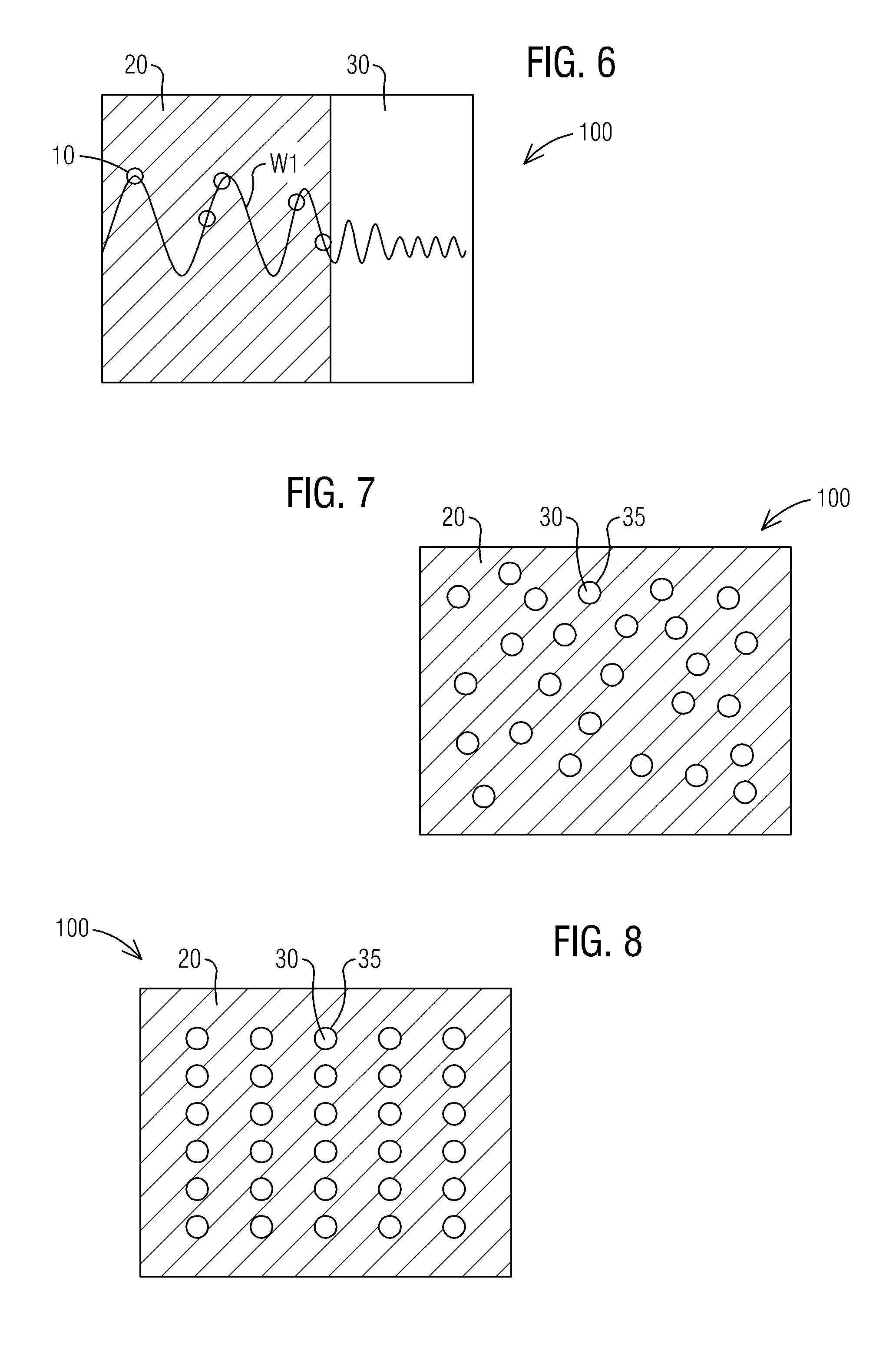
[0015] FIG. 7 is a diagram illustrating a material having phononic regions formed of void nanostructures that are void spheres in a random distribution.
[0016] FIG. 8 is a diagram illustrating a material having phononic regions formed of void nanostructures that are void spheres in an ordered arrangement.
[0017] FIG. 9 is a diagram illustrating boundaries of phononic regions of void nanostructures that are void columns.
[0018] FIG. 10 shows an example of a nanomesh formed on the material of a gas turbine engine component.
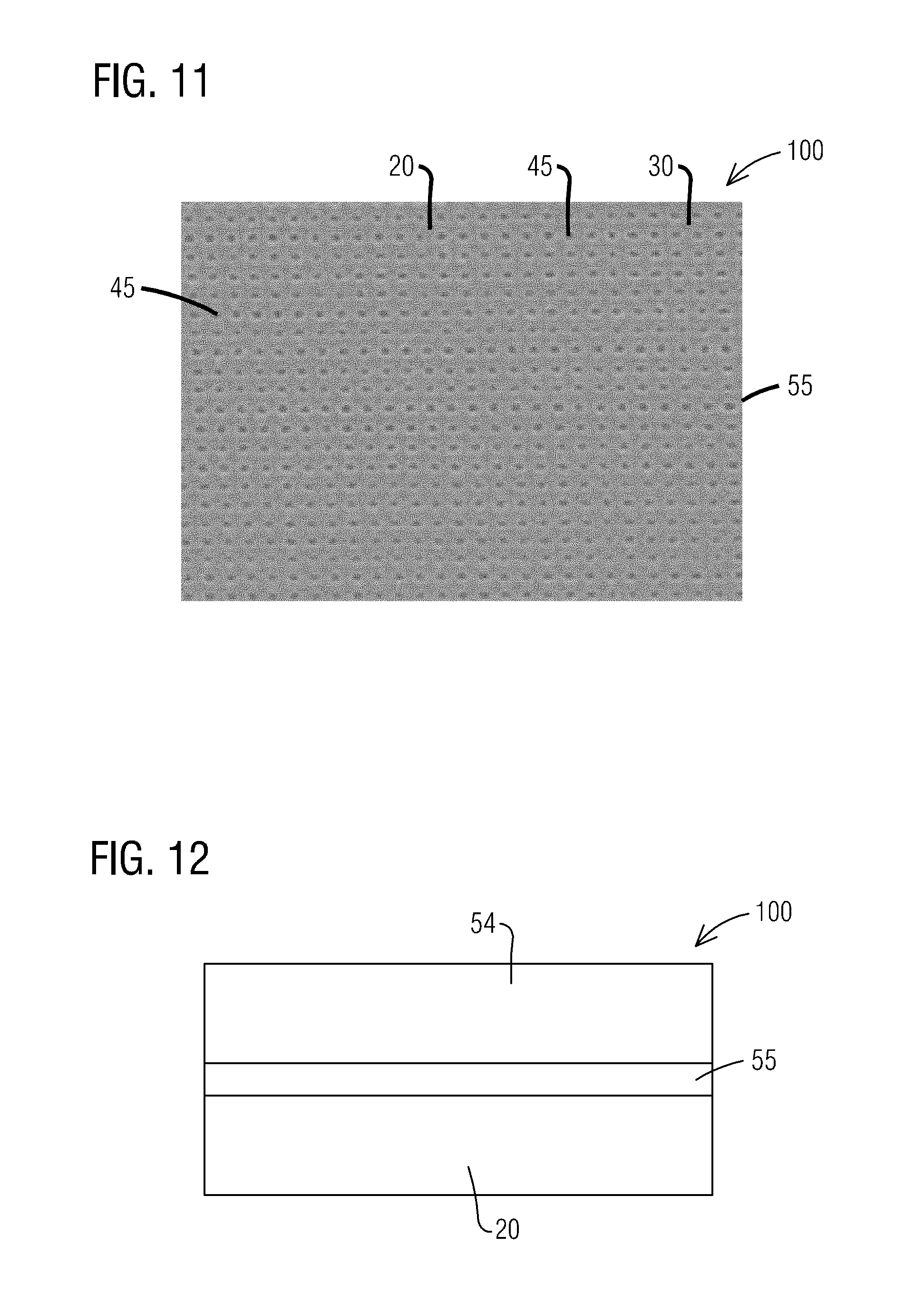
[0019] FIG. 11 shows an example of a nanomesh grid formed on the material of a gas turbine engine component.
[0020] FIG. 12 shows a diagram of a nanomesh grid formed on the material of a gas turbine engine component.
DETAILED DESCRIPTION
[0021] To facilitate an understanding of embodiments, principles, and features of the present disclosure, they are explained hereinafter with reference to implementation in illustrative embodiments. Embodiments of the present disclosure, however, are not limited to use in the described systems or methods.
[0022] The items described hereinafter as making up the various embodiments are intended to be illustrative and not restrictive. Many suitable items that would perform the same or a similar function as the items described herein are intended to be embraced within the scope of embodiments of the present disclosure.
[0023] As disclosed herein, the materials used in the gas turbine engines permit the thermal conductivity of pieces to be modified, such as by being reduced in size, without changing the chemical structure in the majority of the material. Management of heat conduction can be achieved through nanostructure modification to portions of the existing gas turbine engine components. There is no need for a large scale bulk material or chemical changes; however smaller scale modifications consistent with aspects of the instant invention may be made to gas turbine engine components.
[0024] FIG. 1 shows a diagram illustrating the transmission of phonons 10 into a material 20 that is forming part of a gas turbine engine component 100 that can be used in a gas turbine engine. The gas turbine engine component 100 may be a transition duct, liner, part of the combustor, vanes, blades, rings and other gas turbine structures for which heat management would be advantageous. It should also be understood that in addition to gas turbine engine components 100, the management of heat conduction disclosed herein can be applied to other devices for which heat management is important, for example, marine based turbines, aerospace turbines boilers, engine bells, heat management devices, internal combustion engines, kilns, smelting operations and any other item wherein heat conduction is a design consideration.
[0025] The material 20 discussed herein is a metallic material, however it should be understood that other types of materials may be used, such as ceramic, metallic glasses and composite materials, when given due consideration for their material properties consistent with aspects of the instant invention. A phonon 10 is generally and herein understood and defined as a quantum of energy associated with a compressional, longitudinal, or other mechanical or electro-mechanical wave such as sound or a vibration of a crystal lattice. Transmissions of phonons 10 collectively transmit heat. The transmissions of phonons 10 form waves in the material 20 as they propagate through the material 20.
[0026] In FIG. 1, the phonons 10 are transmitted through the material 20 at a first phononic wave W1. Formed in the material 20 is a phononic region 30. The phononic region 30 is designed to modify the behavior of the phonons 10 as they propagate in the one dimensional (1D), two dimensional (2D) and/or three dimensional (3D) spatial regions in the material 20. The phononic region 30 may modify the behavior of phonons 10 so that they scatter, change direction, change between propagation modes (e.g. change from compression waves to travelling waves), reflect, refract, filter by frequency, and/or dissipate. The modification of the behavior of the phonons 10 manages the heat conduction in the gas turbine engine component 100. The phononic region 30 is a void nanostructure formed within the material 20. The void nanostructure is designed to be placed within the material 20 in such a manner as to modify the behavior of phonons 10 as they propagate through the material 20 so that heat conduction through the material 20 is controlled. The void nanostructures can be formed as divots, void spheres, void channels or other modifications to the material.
[0027] Still referring to FIG. 1, the modification of behavior of the phonons 10 by the phononic region 30 may create a second phononic wave W2. For example, the first phononic wave W1 propagates through the material 20. As the first phononic wave W1 propagates through the material 20 the first phononic wave W1 may have the property of having a first frequency .lamda..sub.1. When the first phononic wave W1 interacts with the phononic region 30 the behavior of the phonons 10 may form a second phononic wave W2 having the property of having a second frequency .lamda..sub.2. As the phonons 10 exit from the phononic region 30 and propagate through the material 20 they may continue to propagate at the first frequency .lamda..sub.1.
[0028] The transition from the first frequency .lamda..sub.1 to the second frequency .lamda..sub.2 and then back to the first frequency .lamda..sub.1, helps manage the heat conduction in the material 20. Further, by interspersing the material 20 with a number of phononic regions 30 the fluctuation can disrupt the transmission of phonons 10 through the material 20 so as to manage the propagation of phonons 10.
[0029] FIG. 2 shows a phononic region 30 that modifies the behavior of the first phononic wave W1 to a second phononic wave W2 by changing the property of its mode of propagation. In FIG. 2 the first phononic wave W1 is altered from a travelling wave to the second phonic wave W2 which is a compression wave. However it should be understood that it is contemplated that compression waves could be modified to become travelling waves. By modifying the mode of propagation of the waves the heat conduction through the material 20 may be managed.
[0030] FIG. 3 shows a phononic region 30 that modifies the behavior of the phonons 10 by altering the direction of propagation. Phonons 10 may be moving in one direction D1 through material 20 and then change direction to direction D2 as they enter into phononic region 30. By modifying the direction of movement of the phonons 10 the heat conduction through the material 20 may be managed.
[0031] FIG. 4 shows a phononic region 30 that modifies the behavior of the phonons 10 so that the phonons 10 are scattered when they enter the phononic region 30 from the material 20. By scattering it is meant that each phonon 10 that enters the phononic region 30 in direction D1 may propagate in a random different direction D2, D3, etc. By modifying the scattering of the phonons 10 the heat conduction through the material 20 may be managed.
[0032] FIG. 5 shows a first phononic wave W1 moving through material 20. When the first phononic wave W1 reaches the phononic region 30 the first phononic wave W1 is modified so that it is refracted and becomes second phononic wave W2 as it passes through the phononic region 30. As the second phononic wave W2 exits the phononic region 30 the phononic wave W2 may be refracted and become a third phononic wave W3. By having the phononic region 30 refract the first phononic wave W1 the heat conduction through the material 20 may be managed.
[0033] FIG. 6 shows the phononic region 30 located within the material 20 causing phonons 10 from the first phononic wave W1 to dissipate as it exits the material 20. By "dissipate" it is meant that at least some of the phonons 10 cease to travel through the phononic region 30 or cease to exist. By having the phononic region 30 dissipate the phonons 10 the heat conduction through the material 20 may be managed.
[0034] FIG. 7 shows an example of the phononic region 30 formed by void nanostructures within the material 20. It should be understood that the void nanostructure forms the entirety of the phononic region 30. However, various phononic regions 30 may be formed from more than one type of void nanostructure. For example, as discussed herein the void nanostructure forming the phononic region 30 may be a void sphere 35 formed within the material 20. In addition to a void sphere 35, other shapes for the void nanostructures may be formed such as void channels 40 or nanovoid divots 45, as well as, amorphous shapes or other polygonal shapes.
[0035] The material 20 may be metallic in nature and may form a gas turbine engine component 100 or the component of another device wherein heat management may be need. Within the material 20 the phononic regions 30 may be formed as void spheres 35 within the material 20. FIG. 7 shows the void spheres 35 randomly dispersed throughout the material 20. The void spheres 35 may have a diameter of between 5 nm-1000 nm. The placement and size of the void spheres 35 is determined based upon how heat conduction in the gas turbine engine component 100 will be managed.
[0036] FIG. 8 shows an alternative embodiment of the phononic regions 30 formed of void nanostructures where the void spheres 35 are positioned within the material in an orderly manner. In this example the void spheres 35 are organized so that they form rows of the void spheres 35. The void spheres 35 may have a diameter of between 5 nm-1000 nm. The placement and size of the void spheres 35 is determined based upon how heat conduction in the gas turbine engine component 100 will be managed.
[0037] FIG. 9 is an alternative embodiment having phononic regions 30 formed as void channels 40 within the material 20. The void channels 40 may have a width of between 5 nm-1000 nm. The length of the void channel 40 may vary depending on the size of the gas turbine engine component 100, however generally a size of between 100 um-10 cm is contemplated. However, the void channel 40 may be between 10 um and 100 cm. The placement and size of the void channels 40 is determined based upon how heat conduction in the gas turbine engine component 100 will be managed.
[0038] Introduction of sharp changes in the acoustic impedance experienced by phonons 10 propagating through the phononic regions 30 can be instantiated by the void spheres 35 or void channels 40 formed in the material 20. The phononic regions 30 can be formed in various layers of the material 20. When the phononic region 30 is incorporated into a subsection of a material 20 with resolutions in the 5-1000 nm range, the void nanostructures that form the phononic region 30 will cause the phonons 10 to behave in one of the manners discussed above in reference to FIGS. 1-6. This size correlates with phononic vibration frequencies of approximately 500 GHz to 100 THZ. Because the phononic regions 30 will have differing phononic impedances than the material 20, they will modify behavior of the propagating phonons 10 in the material 20, thereby disrupting, reducing and/or managing heat conduction. These techniques can also be used to direct heat conduction in desired directions by creating paths of optimal propagation for heat-inducing phonons 10 that are surrounded by phononic regions 30.
[0039] In each of the above possible ways of managing the heat conduction shown in FIGS. 1-6, phonons 10 interacting with phononic regions 30 on the same scale as their wavelength, can modify behavior of phonons 10 to impede propagation of phonons 10 and thus manage heat conduction. The patterns formed by the phononic regions 30 can be used to obtain the modified behavior of the phonons 10 that is desired. For example, patterns of phononic regions 30 parallel to the propagation direction can channel the phonons 10. Patterns of phononic regions 30 normal to the phonons 10 can reflect them. Patterns of phononic regions 30 at an angle with respect to the propagation direction can scatter or reflect at an angle, spots of acoustic impedance change could cause scattering, etc.
[0040] As discussed above the phononic regions 30 may be used in metals and other crystalline structures, as well as ceramics in which void nanostructures may be created. In metals especially at temperatures above 400.degree. C., the majority carrier is electrons. The technique for modifying behavior of the phonons 10 is likely to manage phonons 10 directly more so than thermal free electrons in metals. However, electron propagation may also be affected by the phononic regions 30, in two possible ways. One, electrons in metals are constantly exchanging their energies with phonons 10, so management of the phonons 10 has an effect on electrical propagation. Two, if the electron propagation has any frequency component, it would likely be of similar frequencies as the phonon 10, due to similar interactions that the electrons will have with crystalline structures. In metals control of phonons 10 may have significant impacts on heat conduction that is mediated by thermal free electrons.
[0041] FIG. 10 shows an example of a nanomesh 50 formed on material 20 of the gas turbine engine component 100. In particular, for example, the nanonmesh 50 may be formed on the surface of a vane. The vane may be a modified vane from an existing gas turbine engine component 100, or alternatively the vane may have been formed with the nanomesh 50. Additionally the design of the vane may be modified from an existing vane design or alternatively designed in such a fashion so as to take advantage of the use of the nanomesh 50. The dark spheres are phononic regions 30 that are void nanostructures formed as void spheres 35 within the material 20 of gas turbine engine component 100. The void spheres 35 have diameters that fall within the range of 5-1000 nm. In the example shown the diameters may be in the range 250 nm-400 nm. By having the void spheres 35, phonons 10 propagating through the material 20 impacting the nanomesh 50 can be managed. The nanomesh 50 can modify the behavior of the phonons 10 by disrupting the propagation and cause the phonons 10 to behave in the manner shown in FIGS. 1-6. The desired behavior can be caused by arranging the nanonmesh 50 to form patterns in the material 20 that they can be used to manage heat conduction.
[0042] FIG. 11 shows an example of a nanomesh grid 55 formed on the surface of a material 20 on the gas turbine engine component 100. For example, a nanomesh grid 55 may be formed on a transition duct. The transition duct may be a modified component from an existing gas turbine engine component 100, or alternatively the transition duct may have been formed with the nanomesh grid 55. Additionally the design of the transition duct may be modified from an existing combustor design or alternatively designed in such a fashion so as to take advantage of the use of the nanomesh grid 55. The nanomesh grid 55 is formed from phononic regions 30 arranged as nanovoid divots 45 within the material 20. The nanovoid divots 45 may be formed by lasers pock-marking the surface of the material 20 and then placing another layer of the material 20 on top of the layer with the nanovoid divots 40 formed. The nanovoid divots 40 may be formed so as to have a diameter of between 5-1000 nm. In the example shown the diameters of nanovoid divots 40 may be in the range of 10 nm-40 nm. By having the nanovoid divots 45, the phonons 10 propagating through the material 20 impacting the nanomesh grid 55 can be managed. The nanomesh grid 55 can modify the behavior of the phonons 10 by disrupting the propagation and cause the phonons 10 to behave in the manner shown in FIGS. 1-6.
[0043] FIG. 12 is diagram illustrating layered placement of a nanomesh grid 55 on a material 20 forming the gas turbine engine component 100. For example, the nanomesh grid 55 may be formed on the interior surface of a combustor. The combustor may be a modified component from an existing gas turbine engine component 100. Additionally the design of the combustor may be modified from an existing combustor design or alternatively designed in such a fashion so as to take advantage of the use of the nanomesh grid 55.
[0044] On the surface of the material 20 the nanomesh grid 55 is formed. The thickness of the material 20 may be between 1 cm to 10 cm. The thickness of the nanomesh grid 55 may be between 5-1000 nm. The nanomesh grid 55 may be formed in one of the manners discussed above, for example the nanomesh grid 55 may be formed by adding nanovoid divots 40 to an existing gas turbine engine component 100. On the surface of the nanomesh grid 55 a thermal barrier 54 may be placed. The thickness of the thermal barrier 54 may be between 1 mm to 5 cm. The thermal barrier 54 may be made of a heat resistant material, such as ceramic. Once formed the layered structure can be used to manage the propagation of the heat from the interior of the combustor. This can help reduce the stresses that heat may generate in the material 20 and can extend the life span of gas turbine engine components 100.
[0045] While embodiments of the present disclosure have been disclosed in exemplary forms, it will be apparent to those skilled in the art that many modifications, additions, and deletions can be made therein without departing from the spirit and scope of the invention and its equivalents, as set forth in the following claims.
* * * * *
D00000
D00001
D00002
D00003
D00004
D00005
XML
uspto.report is an independent third-party trademark research tool that is not affiliated, endorsed, or sponsored by the United States Patent and Trademark Office (USPTO) or any other governmental organization. The information provided by uspto.report is based on publicly available data at the time of writing and is intended for informational purposes only.
While we strive to provide accurate and up-to-date information, we do not guarantee the accuracy, completeness, reliability, or suitability of the information displayed on this site. The use of this site is at your own risk. Any reliance you place on such information is therefore strictly at your own risk.
All official trademark data, including owner information, should be verified by visiting the official USPTO website at www.uspto.gov. This site is not intended to replace professional legal advice and should not be used as a substitute for consulting with a legal professional who is knowledgeable about trademark law.