Voltage Converting Unit
WATARU; Kazuhisa ; et al.
U.S. patent application number 15/960660 was filed with the patent office on 2019-01-24 for voltage converting unit. This patent application is currently assigned to Yazaki Corporation. The applicant listed for this patent is Yazaki Corporation. Invention is credited to Katsuyuki IWASAKI, Kazuhisa WATARU.
| Application Number | 20190028017 15/960660 |
| Document ID | / |
| Family ID | 64951484 |
| Filed Date | 2019-01-24 |
| United States Patent Application | 20190028017 |
| Kind Code | A1 |
| WATARU; Kazuhisa ; et al. | January 24, 2019 |
VOLTAGE CONVERTING UNIT
Abstract
Provided is a voltage converting unit including: a voltage converter capable of bidirectionally supplying electrical power between a first power system and a second power system; and a bypass switch disposed in parallel to the voltage converter. The voltage converter includes: a detector detecting a difference in voltage between the first power system and the second power system; and a switch controller controlling switching of the bypass switch on the basis of the difference in voltage in accordance with a predetermined rule.
| Inventors: | WATARU; Kazuhisa; (Makinohara-shi, JP) ; IWASAKI; Katsuyuki; (Makinohara-shi, JP) | ||||||||||
| Applicant: |
|
||||||||||
|---|---|---|---|---|---|---|---|---|---|---|---|
| Assignee: | Yazaki Corporation Tokyo JP |
||||||||||
| Family ID: | 64951484 | ||||||||||
| Appl. No.: | 15/960660 | ||||||||||
| Filed: | April 24, 2018 |
| Current U.S. Class: | 1/1 |
| Current CPC Class: | H02J 7/1423 20130101; B60R 16/03 20130101; H02J 2310/46 20200101; H02M 2001/0009 20130101; H02J 2310/40 20200101; H02M 1/08 20130101; H02J 1/082 20200101; H02J 7/00 20130101 |
| International Class: | H02M 1/08 20060101 H02M001/08 |
Foreign Application Data
| Date | Code | Application Number |
|---|---|---|
| Jul 19, 2017 | JP | 2017-139635 |
Claims
1. A voltage converting unit comprising: a voltage converter capable of bidirectionally supplying electric power between a first power system and a second power system; and a bypass switch disposed in parallel to the voltage converter, wherein the voltage converter includes: a detector detecting a difference in voltage between the first power system and the second power system; and a switch controller controlling switching of the bypass switch based on the difference in voltage in accordance with a predetermined rule.
2. The voltage converting unit according to claim 1, wherein the detector further detects a current flowing between the first power system and the second power system, and the switch controller further controls switching of the bypass switch based on the current.
3. The voltage converting unit according to claim 1, wherein the detector further detects a temperature, and the switch controller further controls switching of the bypass switch based on the temperature.
4. The voltage converting unit according to claim 2, wherein the detector further detects a temperature, and the switch controller further controls switching of the bypass switch based on the temperature.
5. The voltage converting unit according to claim 1, wherein the rule is determined through a comparison between power consumption in the bypass switch while the bypass switch is turned on and power consumption in the voltage converter while the bypass switch is turned off.
6. The voltage converting unit according to claim 2, wherein the rule is determined through a comparison between power consumption in the bypass switch while the bypass switch is turned on and power consumption in the voltage converter while the bypass switch is turned off.
7. The voltage converting unit according to claim 3, wherein the rule is determined through a comparison between power consumption in the bypass switch while the bypass switch is turned on and power consumption in the voltage converter while the bypass switch is turned off.
8. The voltage converting unit according to claim 4, wherein the rule is determined through a comparison between power consumption in the bypass switch while the bypass switch is turned on and power consumption in the voltage converter while the bypass switch is turned off.
9. The voltage converting unit according to claim 5, wherein the rule is further determined through a comparison between operational stability of the voltage converter while the bypass switch is turned on and operational stability of the voltage converter while the bypass switch is turned off.
10. The voltage converting unit according to claim 6, wherein the rule is further determined through a comparison between operational stability of the voltage converter while the bypass switch is turned on and operational stability of the voltage converter while the bypass switch is turned off.
11. The voltage converting unit according to claim 7, wherein the rule is further determined through a comparison between operational stability of the voltage converter while the bypass switch is turned on and operational stability of the voltage converter while the bypass switch is turned off.
12. The voltage converting unit according to claim 8, wherein the rule is further determined through a comparison between operational stability of the voltage converter while the bypass switch is turned on and operational stability of the voltage converter while the bypass switch is turned off.
Description
BACKGROUND
Technical Field
[0001] The present invention relates to a voltage converting unit including a voltage converter.
Related Art
[0002] Recent automobiles and other automatic vehicles each include two power systems having different voltages from each other. For example, a power system of 48 V is mounted in addition to a conventional power system of 12 V.
[0003] Mutual transfer of electric power between the two systems having different voltages allows one of the power systems to compensate for a shortage of power in the other power system in failure. The mutual transfer of electric power also allows a battery of one of the power systems to be charged with a battery of the other power system. To achieve the mutual transfer of electric power, the use of bidirectional voltage converters such as bidirectional DCDC converters has been proposed.
[0004] Patent Literature 1: JP 2016-226199 A
SUMMARY
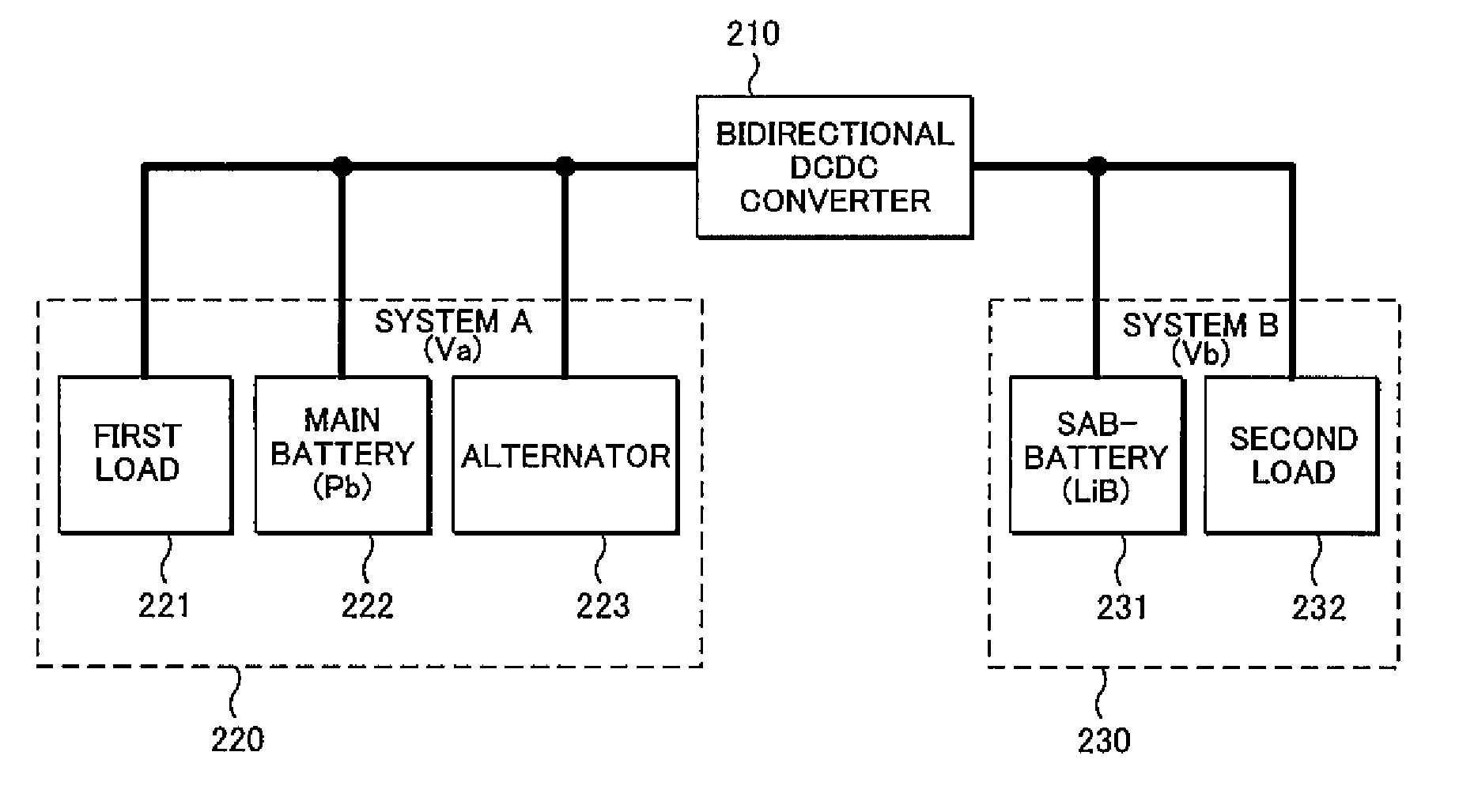
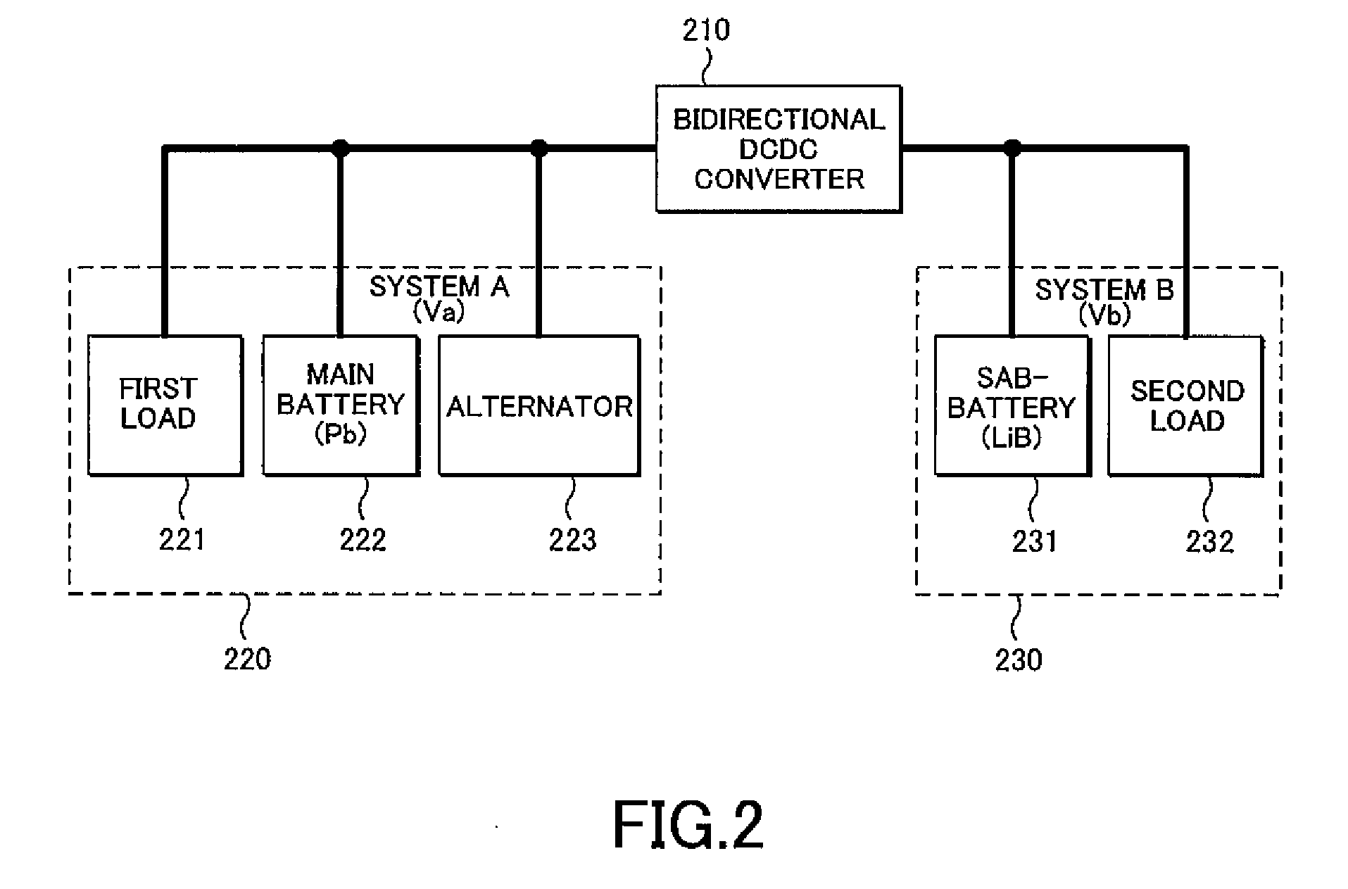
[0005] FIG. 2 illustrates a bidirectional DCDC converter 210 disposed between a power system A 220 and a power system B 230. With reference to FIG. 2, the power system A 220 includes a first load 221, a main battery (Pb) 222, and an alternator 223. The power system B 230 includes a sub-battery (Lib) 231 and a second load 232.
[0006] Herein, a voltage Vb of the power system B 230 is higher than a voltage Va of the power system A 220. It is to be noted that the voltages Va and Vb are variable depending on conditions of the batteries, loads, and other components of the respective power systems.
[0007] For power supply from the power system A 220 to the power system B 230, the bidirectional DCDC converter 210 increases the voltage Va to around the voltage Vb. In contrast, for power supply from the power system B 230 to the power system A 220, the bidirectional DCDC converter 210 reduces the voltage Vb to around the voltage Va.
[0008] For example, in a case where a difference between the voltage Vb of the power system B 230 and the voltage Va of the power system A 220 is small, voltage conversion is not necessarily required for the power supply from the power system B 230 to the power system A 220.
[0009] In such a case, power supply via the bidirectional DCDC converter 210 consumes electric power to operate the bidirectional DCDC converter 210, resulting in a waste of electric power. To contribute to an improvement in fuel efficiency of vehicles, for example, it is preferred to reduce power consumption in a voltage converter, such as the bidirectional DCDC converter 210, during the power transfer.
[0010] An object of the present invention is thus to reduce power consumption in a voltage converter during power transfer between power systems.
[0011] To address the problems described above, a voltage converting unit according to an aspect of the present invention includes: a voltage converter capable of bidirectionally supplying electric power between a first power system and a second power system; and a bypass switch disposed in parallel to the voltage converter. The voltage converter includes: a detector detecting a difference in voltage between the first power system and the second power system; and a switch controller controlling switching of the bypass switch on the basis of the difference in voltage in accordance with a predetermined rule.
[0012] If the difference in voltage satisfies a condition defined by the rule, the power supply can be performed without the voltage converter. This allows for a reduction in power consumption in the voltage converter during the power transfer between the power systems.
[0013] The detector may further detect a current flowing between the first power system and the second power system, and the switch controller may further control switching of the bypass switch on the basis of the current.
[0014] This configuration is designed for the case where power consumption varies depending on currents flowing between the first power system and the second power system.
[0015] Additionally, the detector may further detect a temperature, and the switch controller may further control switching of the bypass switch on the basis of the temperature.
[0016] This configuration is designed for the case where the power consumption varies depending on temperatures.
[0017] The rule may be determined through a comparison between power consumption in the bypass switch while the bypass switch is turned on and power consumption in the voltage converter while the bypass switch is turned off.
[0018] Accordingly, a path that requires less power consumption is selected from the path via the voltage converter and the path via the bypass switch.
[0019] The rule may be further determined through a comparison between operational stability of the voltage converter while the bypass switch is turned on and operational stability of the voltage converter while the bypass switch is turned off.
[0020] This can prevent unstable operation of the voltage converter.
[0021] According to embodiments of the present invention, power consumption in a voltage converter can be reduced during power transfer between power systems.
BRIEF DESCRIPTION OF DRAWINGS
[0022] FIG. 1 is a configurational diagram of a voltage converting unit according to an embodiment of the present invention; and
[0023] FIG. 2 illustrates a bidirectional DCDC converter disposed between a power system A and a power system B.
DETAILED DESCRIPTION
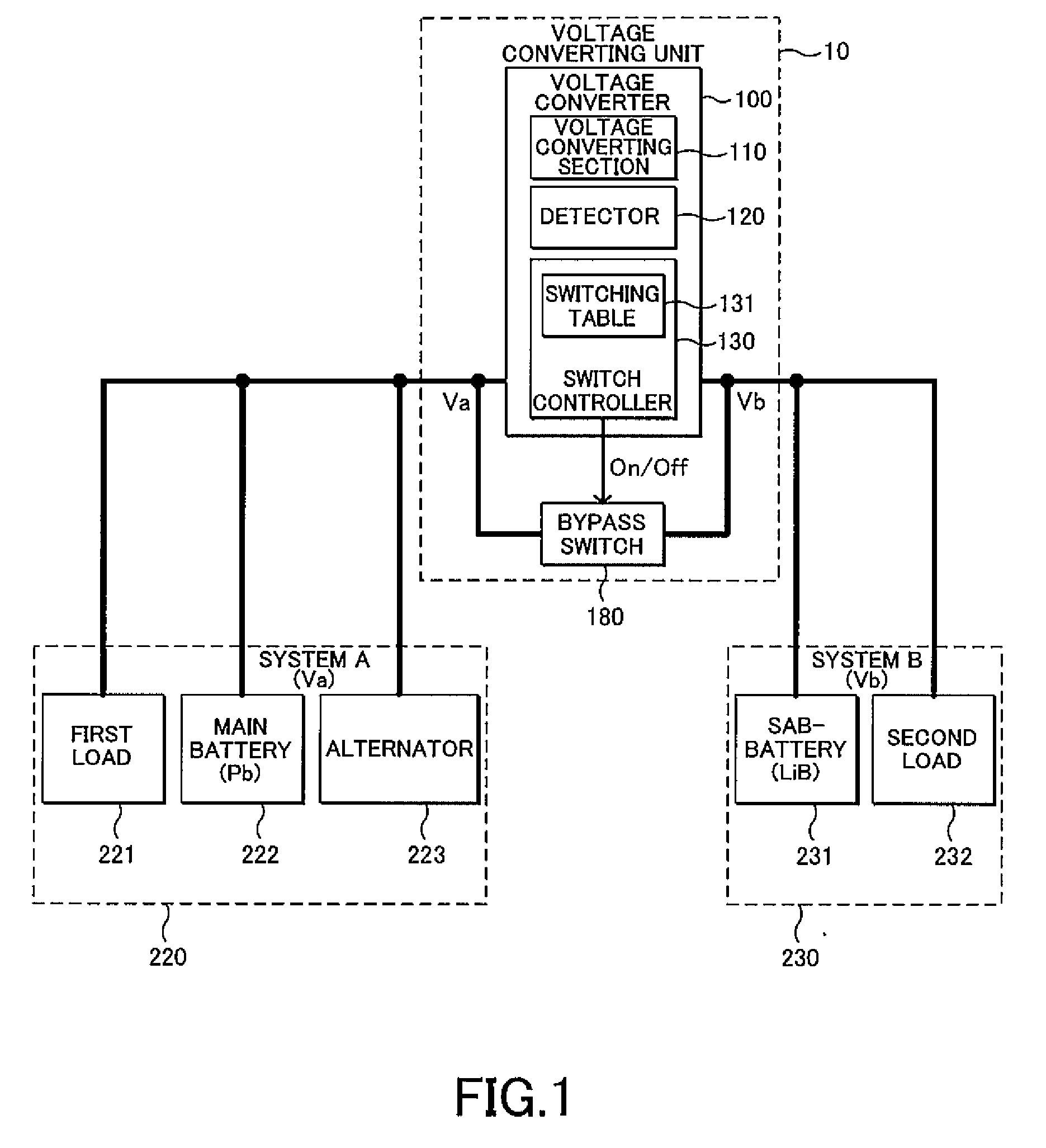
[0024] Embodiments of the present invention will now be described in detail with reference to the drawings. FIG. 1 is a configurational diagram of a voltage converting unit 10 according to an embodiment of the present invention. With reference to FIG. 1, the voltage converting unit 10 is disposed between a power system A 220 and a power system B 230 and transfers electric power between the power system A 220 and the power system B 230. Herein, a connection terminal coupled to the power system A 220 is referred to as "connection terminal A", and a connection terminal coupled to the power system B 230 is referred to as "connection terminal B".
[0025] The power system A 220 includes a first load 221, a main battery (Pb) 222, and an alternator 223. The power system B 230 includes a sub-battery (Lib) 231 and a second load 232. A voltage Vb of the power system B 230 is higher than a voltage Va of the power system A 220 . It is to be noted that the voltages Va and Vb are variable depending on conditions of the batteries, loads, and other components of the respective power systems.
[0026] The voltage converting unit 10 includes a voltage converter 100 and a bypass switch 180. The bypass switch 180 may be a semiconductor switch, for example, and is coupled in parallel to the voltage converter 100. The bypass switch 180 has an on-resistance while being turned on. In view of a reduction in power consumption, a lower on-resistance is preferred.
[0027] As illustrated in FIG. 1, the voltage converter 100 includes a voltage converting section 110, a detector 120, and a switch controller 130. The switch controller 130 includes a switching table 131.
[0028] The voltage converting section 110 performs bidirectional voltage conversion between the connection terminal A and the connection terminal B. The voltage converting section 110 may be a bidirectional DCDC converter, for example. The voltage converting section 110 may have any voltage converting scheme. Examples of the scheme may include a linear regulator scheme, a chopper circuit scheme, and a switching regulator scheme.
[0029] The detector 120 detects physical quantities inside and outside the voltage converting unit 10. The physical quantities to be detected may be a voltage Va of the power system A 220 coupled to the connection terminal A, and a voltage Vb of the power system B 230 coupled to the connection terminal B. The detector 120 may further detect a temperature at and in the vicinity of the voltage converting unit 10. Additionally, the detector 120 may detect a current flowing between the power system A 220 and the power system B 230 via the voltage converting unit 10.
[0030] If the voltage conversion at the voltage converting unit 10 is not needed, the switch controller 130 performs on/off control of the bypass switch 180 on the basis of a result of the detection by the detector 120. It is to be noted that the need for the voltage conversion at the voltage converting unit 10 may be determined on the basis of an instruction from a host device, for example. The switch controller 130 controls on/off of the bypass switch 180 with reference to the switching table 131.
[0031] The switching table 131 defines on/off of the bypass switch 180 in a correlation with a difference in voltage dV between the voltage Va and the voltage Vb. In detail, if the difference in voltage dV between the voltage Va and the voltage Vb falls within a range defined by the switching table 131, the switch controller 130 turns on the bypass switch 180, and otherwise turns off the bypass switch 180.
[0032] The switch controller 130 may be a processor such as a microcomputer, for example. The switching table 131 may be stored in a memory in a microcomputer, for example.
[0033] While the bypass switch 180 is turned off, power supply between the power system A 220 and the power system B 230 via the voltage converting unit 10 is performed via the voltage converter 100. In this case, power required to operate the voltage converting section 110 corresponds to power consumption.
[0034] While the bypass switch 180 is turned on, the power supply between the power system A 220 and the power system B 230 via the voltage converting unit 10 is performed via the bypass switch 180. Since the bypass switch 180 has an on-resistance, the product of a current through the bypass switch 180 and the difference in voltage dV, or the value obtained from dividing the square of the difference in voltage dV by the on-resistance, corresponds to power consumption.
[0035] The switching table 131 defines on/off of the bypass switch 180 in a correlation with a difference in voltage dV to reduce power consumption. In detail, power consumption while the bypass switch 180 is turned off and power consumption while the bypass switch 180 is turned on are preliminary determined, for each difference in voltage dV, from the specifications, measured values, or other parameters of the voltage converting section 110 and the bypass switch 180 to prepare the switching table 131. With reference to the switching table 131, a path requiring less power consumption is selected.
[0036] For example, if the specifications are the voltage converting section 110 of 3 kW, a difference in voltage of dV1, and a conversion efficiency of the voltage converting section 110 of 97%, the power consumption in the voltage converting section 110 is 90 W (calculated by 3 kW.times.(1-0.97)). In contrast, if the bypass switch 180 has an on-resistance of 1 m .OMEGA., the power consumption in the bypass switch 180 is (dV1 2/0.001) W. If the power consumption in the bypass switch 180 is less than that in the voltage converting section 110, the switching table 131 defines that the bypass switch 180 is to be turned on at the difference in voltage dV1.
[0037] Accordingly, the switching table 131 may follow a format in which the bypass switch 180 is turned on if the relations V1<dV<V2 and V3<dV<V4 are satisfied, for example. It is needless to mention that the switching table 131 may be defined by another format.
[0038] The voltage converting section 110 may exhibit unstable behavior while the difference in voltage dV is small, for example. The voltage converting section 110 may repeat step-up and step-down operations, for example, resulting in an increase in ripple voltage and fluctuation in voltage.
[0039] To prevent the unstable behavior, the switching table 131 may define that the bypass switch 180 is to be turned on if the difference in voltage dV falls within a range where the voltage converting section 110 causes unstable behavior, regardless of the amount of power consumption. This can prevent unstable behavior of the voltage converting section 110. In this case, the switching table 131 may contain an additional rule which defines that the bypass switch 180 is to be turned on if the relation V5<dV<V6 is satisfied.
[0040] The power consumption in the voltage converting section 110 and that in the bypass switch 180 may be affected by factors other than the difference in voltage dV. For example, in a case where the power consumption varies depending on ambient temperatures, a switching table 131 is prepared for each ambient temperature.
[0041] In this case, the detector 120 detects an ambient temperature, and the switch controller 130 performs on/off control of the bypass switch 180 on the basis of one of the switching tables 131 that corresponds to the detected ambient temperature. For example, a switching table 131 may be prepared for every five degrees in temperature, and one of the switching tables 131 that corresponds to the detected temperature is used.
[0042] In another case where the power consumption varies depending on currents flowing through the voltage converting section 110, the switching table 131 is prepared for each current. In this case, the detector 120 detects a current flowing between the connection terminal A and the connection terminal B of the voltage converting unit 10, and the switch controller 130 performs on/off control of the bypass switch 180 on the basis of one of the switching tables 131 that corresponds to the detected current.
[0043] In still another case, the switching table 131 may be prepared for each type of batteries of the power systems. For example, a switching table 131 may be prepared for each type (lead, lithium ion, and capacitor, etc.) of the sub-battery 231 of the power system B 230.
[0044] According to the voltage converting unit 10 of the embodiment described above, the detector 120 detects a difference in voltage between the power systems, and the switch controller 130 controls switching of the bypass switch 180 on the basis of the difference in voltage. This allows for power supply without the voltage converting section 110, resulting in a reduction in power consumption in the voltage converter 100 during power transfer between the power systems.
REFERENCE SIGNS LIST
[0045] 10 voltage converting unit [0046] 100 voltage converter [0047] 110 voltage converting section [0048] 120 detector [0049] 130 switch controller [0050] 131 switching table [0051] 180 bypass switch [0052] 220 power system A [0053] 222 main battery [0054] 230 power system B [0055] 231 sub-battery
* * * * *
D00000
D00001
D00002
XML
uspto.report is an independent third-party trademark research tool that is not affiliated, endorsed, or sponsored by the United States Patent and Trademark Office (USPTO) or any other governmental organization. The information provided by uspto.report is based on publicly available data at the time of writing and is intended for informational purposes only.
While we strive to provide accurate and up-to-date information, we do not guarantee the accuracy, completeness, reliability, or suitability of the information displayed on this site. The use of this site is at your own risk. Any reliance you place on such information is therefore strictly at your own risk.
All official trademark data, including owner information, should be verified by visiting the official USPTO website at www.uspto.gov. This site is not intended to replace professional legal advice and should not be used as a substitute for consulting with a legal professional who is knowledgeable about trademark law.