Assembling Apparatus
Deng; Yingcong ; et al.
U.S. patent application number 16/139124 was filed with the patent office on 2019-01-24 for assembling apparatus. This patent application is currently assigned to Tyco Electronics (Shanghai) Co. Ltd.. The applicant listed for this patent is Tyco Electronics (Shanghai) Co. Ltd., Tyco Electronics (Zhuhai) Ltd.. Invention is credited to Wei Chen, Zhiyong Dai, Yingcong Deng, Lvhai Hu, Yun Liu, Qiang Yu, Dandan Zhang, Ning Zhang.
| Application Number | 20190027885 16/139124 |
| Document ID | / |
| Family ID | 58579227 |
| Filed Date | 2019-01-24 |


| United States Patent Application | 20190027885 |
| Kind Code | A1 |
| Deng; Yingcong ; et al. | January 24, 2019 |
Assembling Apparatus
Abstract
An assembling apparatus adapted to assemble a case made of thin plate. The case comprises a bottom case and a top case, a latch is formed on each side wall of the bottom case, and a locking spring is formed on each side plate of the top case. When the side plates of the top case are located at a predetermined position with respect to the top wall of the top case, the lock springs are adapted to be fitted into the latches from inner sides of the latches, respectively. The assembling apparatus comprises: a base configured to position and support the bottom case; an operation mechanism adapted to hold and move the top case; and a guide device adapted to be disposed at the inner side of the latch and configured to guide the side plate to the predetermined position, so that the lock spring on the side plate of the top case is capable of being fitted into the latch. In the present invention, the guide device may automatically correct the position deviation of the side plates of the top case by guiding the side plates offset from a predetermined position to the predetermined position. As a result, the lock spring on the side plate of the top case is smoothly fitted into the latch, improving the assembly efficiency of the case made of thin plate.
| Inventors: | Deng; Yingcong; (Shanghai, CN) ; Hu; Lvhai; (Shanghai, CN) ; Dai; Zhiyong; (Shanghai, CN) ; Liu; Yun; (Shanghai, CN) ; Zhang; Dandan; (Shanghai, CN) ; Yu; Qiang; (Zhuhai, CN) ; Chen; Wei; (Zhuhai, CN) ; Zhang; Ning; (Zhuhai, CN) | ||||||||||
| Applicant: |
|
||||||||||
|---|---|---|---|---|---|---|---|---|---|---|---|
| Assignee: | Tyco Electronics (Shanghai) Co.
Ltd. Shanghai CN Tyco Electronics (Zhuhai) Ltd. Zhuhai CN |
||||||||||
| Family ID: | 58579227 | ||||||||||
| Appl. No.: | 16/139124 | ||||||||||
| Filed: | September 24, 2018 |
Related U.S. Patent Documents
| Application Number | Filing Date | Patent Number | ||
|---|---|---|---|---|
| PCT/IB2017/051635 | Mar 21, 2017 | |||
| 16139124 | ||||
| Current U.S. Class: | 1/1 |
| Current CPC Class: | H01R 43/18 20130101 |
| International Class: | H01R 43/18 20060101 H01R043/18 |
Foreign Application Data
| Date | Code | Application Number |
|---|---|---|
| Mar 22, 2016 | CN | 201610164692.2 |
Claims
1. An assembling apparatus for assembly of a case made of thin plate and comprising: a bottom case having side plates and side walls; a top case having a top wall and side plates; a latch on each side wall of the bottom case; and a locking spring on each side plate of the top case fitted into the latches from an inner side of the latches, respectively, when the side plates of the top case are at a predetermined position with respect to the top wall of the top case; and the assembling apparatus comprising: a base configured to position and support the bottom case; an operation mechanism adapted to hold and move the top case; and a guide device adapted to be disposed at the inner side of the latch and configured to guide the side plate to the predetermined position, so that the lock spring on the side plate of the top case is fitted into the latch smoothly.
2. The assembling apparatus according to claim 1, wherein the guide device has a first guide surface facing the inner side of the latch and is adapted to push the side plates outward, so as to gradually expand the distance between the side plates.
3. The assembling apparatus according to claim 2, wherein the guide device has a second guide surface facing the first guide device and is adapted to push the side plates inward, so as to gradually narrow the distance between the side plates.
4. The assembling apparatus according to claim 3, wherein when the side plates are located at the predetermined position, the side plates are perpendicular to a top surface of the top case and a bottom surface of the bottom case.
5. The assembling apparatus according to claim 4, wherein the case further comprises at least one partition plate having a lower side adapted to be assembled to a bottom wall of the bottom case and an upper side adapted to be assembled to the top wall of the top case, so as to divide a space between the bottom case and the top case into a plurality of receiving chambers.
6. The assembling apparatus according to claim 5, further comprising a holding mechanism configured to hold the partition plate in a position where the partition plate is perpendicular to the bottom wall of the bottom case.
7. The assembling apparatus according to claim 6, wherein the holding mechanism comprises at least one pair of clamping fingers each adapted to clamp the partition plate from both sides thereof.
8. The assembling apparatus according to claim 7, wherein the holding mechanism further comprises a first driving mechanism adapted to drive the at least one pair of clamping fingers to move in a direction parallel to the partition plate, so as to move the at least one pair of clamping fingers to or from the partition plate.
9. The assembling apparatus according to claim 8, wherein the holding mechanism further comprises a second driving mechanism adapted to drive the at least one pair of clamping fingers to close or open, so as to clamp or release the partition plate.
10. The assembling apparatus according to claim 9, wherein the first driving mechanism is further adapted to drive the guide device to move in a horizontal direction parallel to the partition plate, so as to move the guide device to or from the latch.
11. The assembling apparatus according to claim 3, wherein the first guide surface and/or the second guide surface are/is formed as a smooth arc guide surface or a smooth slope guide surface.
12. The assembling apparatus according to claim 3, wherein the first guide device is a rigid block with a stiffness larger than that of the side plates and the second guide device is a flexible sheet with a flexibility larger than that of the side plates.
13. The assembling apparatus according to claim 1, wherein the operation mechanism comprises a robot adapted to pick up the top case by vacuum pick up and move the top case.
14. The assembling apparatus according to claim 13, wherein: (a) the top case has a plurality of first holes, and (b) the operation mechanism has a plurality of first position posts adapted to be inserted into the first plurality of holes, respectively, so as to position the top case for vacuum pick up.
15. The assembling apparatus according to claim 14, wherein the bottom case has a plurality of second holes and the base has a plurality of second position posts adapted to be inserted into the plurality of second holes, respectively, so as to position the bottom case supported on the base.
Description
CROSS-REFERENCE TO RELATED APPLICATION
[0001] This application is a continuation of PCT International Application PCT/IB2017/051635 filed Mar. 21, 2017, which claims priority under 35 U.S.C. .sctn. 119 to CN 201610164692.2 filed on Mar. 22, 2016.
FIELD OF THE INVENTION
[0002] The present invention relates, in general, to an assembling apparatus, and, in particular, to an assembling apparatus adapted to assemble a case made of thin plate.
BACKGROUND
[0003] FIG. 1 is an illustrative perspective view of a typical case of a connector viewed from a bottom side and FIG. 2 is an illustrative perspective view the case of FIG. 1 viewed from a top side.
[0004] As shown in FIGS. 1 and 2, the case mainly comprises a bottom case 10, a top case 20 located above the bottom case 10 and at least one partition plate 30 provided between the bottom case 10 and the top case 20. The bottom case 10, the top case 20 and the partition plate 30 are all made of thin metal plate. The thin metal plate is easy to deform, therefore, in the process of machining, the side plates 21 of the top case 20 are easy to offset from a predetermined position, that is, a vertical position where the side plates 21 are perpendicular to the top wall of the top case 20. For example, the side plates 21 may slightly offset outward or slightly offset inward.
[0005] As shown in FIGS. 1 and 2, a latch 12 is formed on each side wall of the bottom case 10 and a locking spring 22 is formed on each side plate 21 of the top case 20. The latches 12 vertically and upwardly extend from both sides of a bottom wall of the bottom case 10, respectively. The side plates 21 vertically and downwardly extend from both sides of a top wall of the top case 20, respectively. The locking spring 22 protrudes outward from the side plate 21 of the top case 20.
[0006] As shown in FIGS. 1 and 2, the lock springs 22 are adapted to be fitted into the latches 12 from inner sides of the latches 12, respectively. In this way, the bottom case 10 and the top case 20 are assembled together.
[0007] A lower side of the partition plate 30 is adapted to be assembled to the bottom wall of the bottom case 10, and an upper side of the partition plate 30 is adapted to be assembled to the top wall of the top case 20. In this way, the space between the bottom case 10 and the top case 20 is divided into a plurality of receiving chambers 1 by the partition plate 30. In an embodiment, the lower side of the partition plate 30 is inserted into a slit formed in the bottom wall of the bottom case 10, and the upper side of the partition plate 30 is inserted into a slit formed in the top wall of the top case 20.
[0008] As shown in FIGS. 1 and 2, if the side plates 21 of the top case 20 offset from the predetermined position, the locking springs 22 on the side plates 21 of the top case 20 cannot be fitted into the latches 12.
[0009] In the prior art, the case shown in FIGS. 1 and 2 is generally assembled manually. Thereby, a worker has to correct the position of the side plates 21 of the top case 20 manually until the side plates 21 of the top case 20 are located in the vertical position where the side plates 21 are perpendicular to the top wall of the top case 20. However, manually correcting the position of the side plates 21 and manually assembling the case greatly reduce the assembly efficiency of the case.
SUMMARY
[0010] The present invention is apparatus for assembling a case made of thin plate. The case has a bottom case having side plates and side walls, a top case having a top wall and side plates, a latch on each side wall of the bottom case, and a locking spring on each side plate of the top case fitted into the latches from an inner side of the latches, respectively, when the side plates of the top case are at a predetermined position with respect to the top wall of the top case. The assembling apparatus comprises a base configured to position and support the bottom case, an operation mechanism adapted to hold and move the top case, and a guide device adapted to be disposed at the inner side of the latch and configured to guide the side plate to the predetermined position, so that the lock spring on the side plate of the top case is fitted into the latch smoothly.
BRIEF DESCRIPTION OF THE DRAWINGS
[0011] The above and other features of the present invention will become more apparent by describing in detail exemplary embodiments thereof with reference to the accompanying drawings, in which:
[0012] FIG. 1 is an illustrative perspective view of a typical case of a connector viewed from a bottom side;
[0013] FIG. 2 is an illustrative perspective view the case of FIG. 1 viewed from a top side;
[0014] FIG. 3 shows an assembling apparatus for assembling the case shown in FIGS. 1 and 2 according to an exemplary embodiment of the present invention;
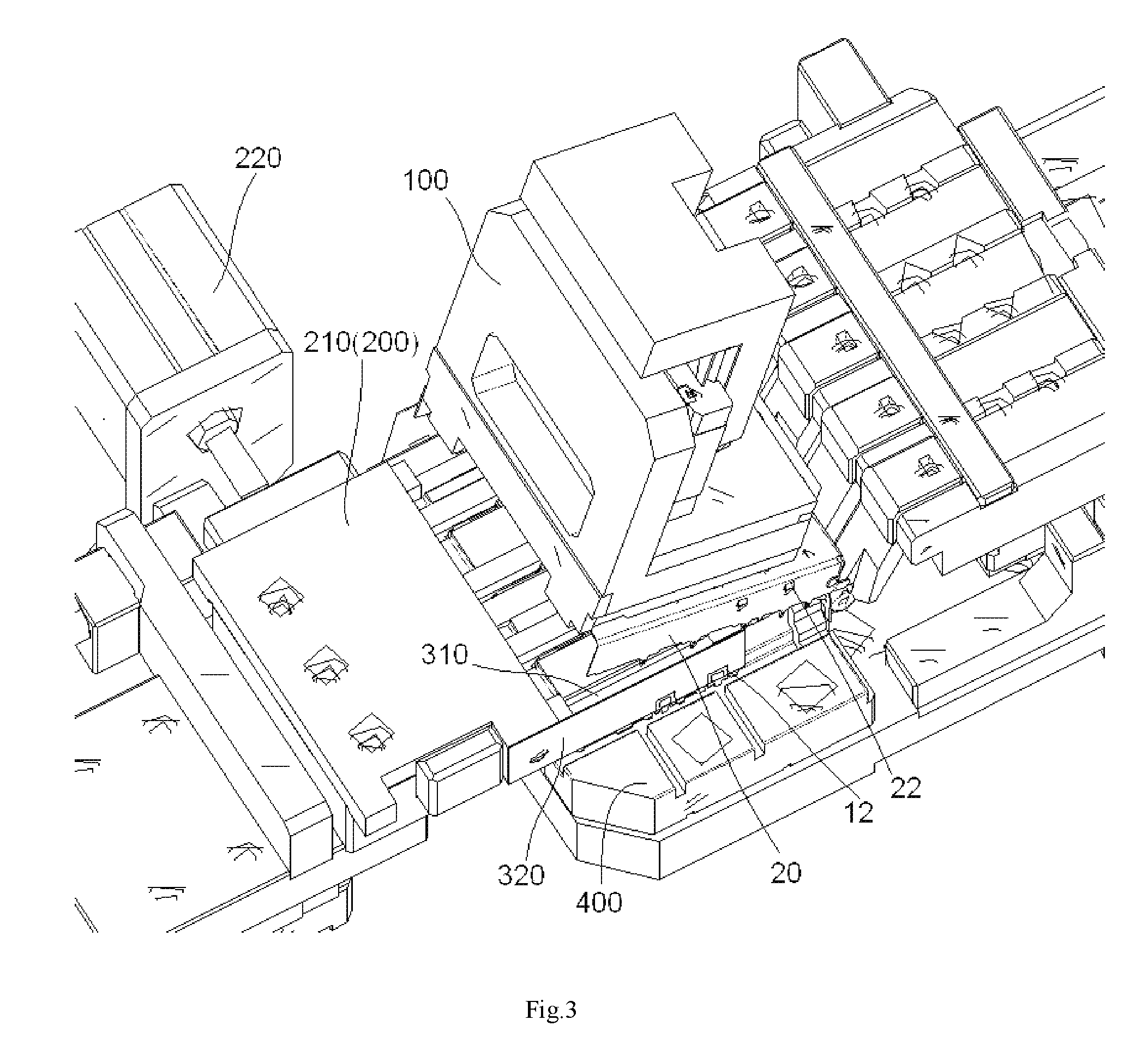
[0015] FIG. 4 shows the assembling apparatus for assembling the case shown in FIGS. 1 and 2 according to the exemplary embodiment of the present invention, in which an operation mechanism is removed;
[0016] FIG. 5 is an illustrative view of correcting a position deviation of the side plates, which are offset inward from a predetermined position, by a first guide device; and
[0017] FIG. 6 is an illustrative view of correcting a position deviation of the side plates, which are offset outward from a predetermined position, by a second guide device.
DETAILED DESCRIPTION OF THE EMBODIMENT(S)
[0018] Exemplary embodiments of the present disclosure will be described hereinafter in detail with reference to the attached drawings, wherein the like reference numerals refer to the like elements. The present invention may, however, be embodied in many different forms and should not be construed as being limited to the embodiments set forth herein; rather, these embodiments are provided so that the disclosure of the present invention will be thorough and complete and will fully convey the concept of the present invention to those skilled in the art.
[0019] In the following detailed description, for purposes of explanation, numerous specific details are set forth in order to provide a thorough understanding of the disclosed embodiments. It will be apparent, however, that one or more embodiments may be practiced without these specific details. In other instances, well-known structures and devices are schematically shown in order to simplify the drawing.
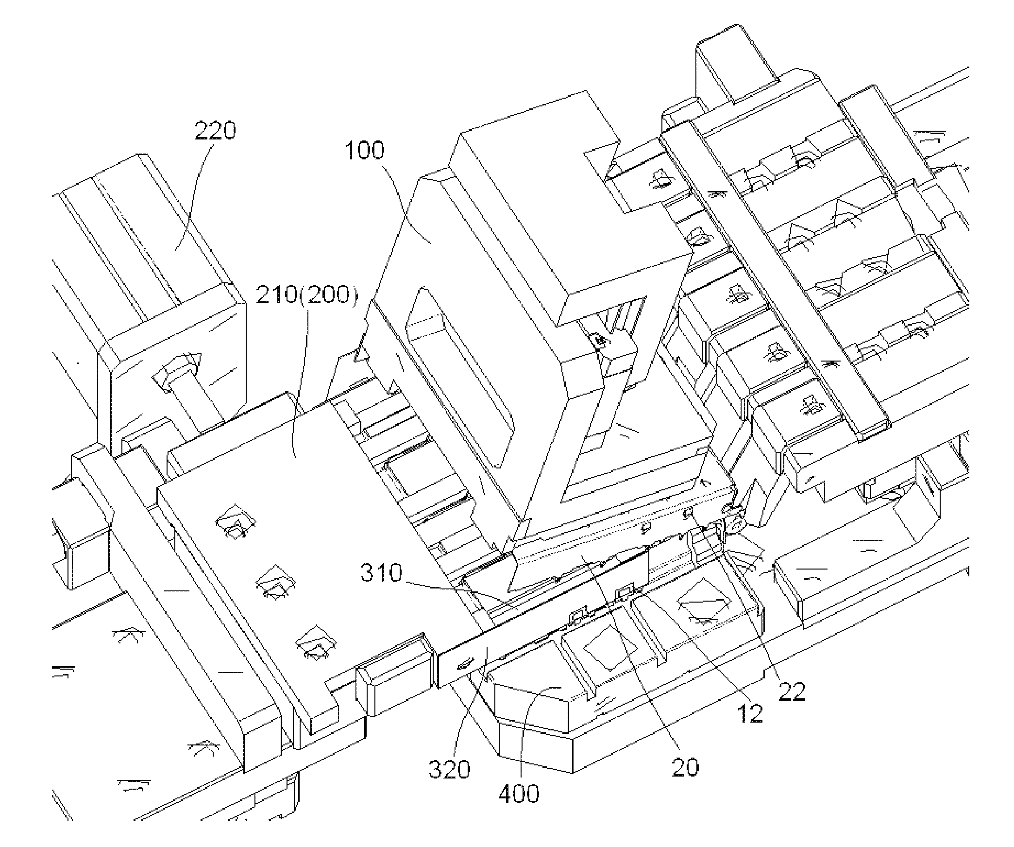
[0020] FIG. 3 shows an assembling apparatus, constructed in accordance with an exemplary embodiment of the present invention, for assembling the case shown in FIGS. 1 and 2, and FIG. 4 shows the assembling apparatus for assembling the case shown in FIGS. 1 and 2 according to the exemplary embodiment of the present invention, in which an operation mechanism 100 is removed.
[0021] As shown in FIGS. 3 and 4, in an embodiment of the present invention, the assembling apparatus mainly comprises an operation mechanism 100, a guide device 310, 320, and a base 400. The bottom case 10 is adapted to be positioned and supported on the base 400. The operation mechanism 100 is configured to hold and move the top case 20, so as to assemble the top case 20 on the bottom case 10. The guide device 310, 320 is disposed at the inner side of the latch 12 and configured to guide the side plate 21 to the predetermined position, so that the lock spring 22 on the side plate 21 of the top case 20 is smoothly fitted into the latch 12. In this way, it may improve the assembly efficiency of the case made of thin plate.
[0022] FIG. 5 is an illustrative view of correcting a position deviation of the side plates 21, which offset inward from a predetermined position, by a first guide device 310.
[0023] As shown in FIGS. 3, 4, and 5, in an embodiment of the present invention, the guide devices 310, 320 comprise a first guide device 310 having a first guide surface S1 facing the inner side of the latch 12. As shown in FIG. 5, when the top case 20 is moved downward, the first guide surface S1 is adapted to push the side plates 21 outward, so as to gradually expand the distance between the side plates 21. In this way, the side plates 21 may be gradually moved to the predetermined position, for example, a vertical position where the side plates 21 are perpendicular to the top wall of the top case 20 and the position deviation of the side plates 21 may be automatically corrected by the first guide device 310. After the side plates 21 are moved to the predetermined position, the lock springs 22 on the side plates 21 of the top case 20 are capable of being smoothly fitted into the latches 12, respectively.
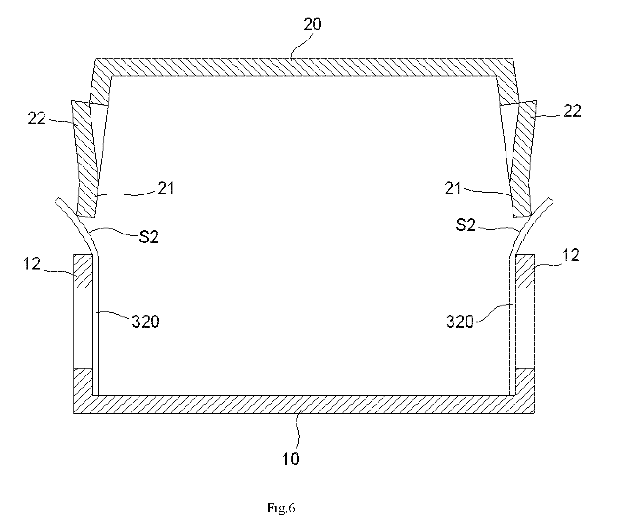
[0024] FIG. 6 is an illustrative view of correcting a position deviation of the side plates 21, which offset outward from a predetermined position, by a second guide device 320.
[0025] As shown in FIGS. 3, 4, and 5, in an embodiment of the present invention, the guide devices 310, 320 further comprise a second guide device 320 having a second guide surface S2 facing the first guide device 310. As shown in FIG. 6, when the top case 20 is moved downward, the second guide surface S2 is adapted to push the side plates 21 inward, so as to gradually narrow the distance between the side plates 21. In this way, the side plates 21 may be gradually moved to the predetermined position, for example, a vertical position where the side plates 21 are perpendicular to the top wall of the top case 20 and the position deviation of the side plates 21 may be automatically corrected by the second guide device 320. After the side plates 21 are moved to the predetermined position, the lock springs 22 on the side plates 21 of the top case 20 are capable of being smoothly fitted into the latches 12, respectively.
[0026] In an exemplary embodiment of the present invention, the first guide device 310 may be formed as a rigid block with a stiffness larger than that of the side plates 21. The second guide device 320 may be formed as a flexible sheet with a flexibility larger than that of the side plates 21. In an embodiment of the present invention, the thickness of the flexible sheet is less than that of the case. Generally, the flexible sheet may be made of alloy, for example, Zinc alloy, with a stiffness less than that of the case.
[0027] It should be noted that, in the embodiment of the present invention shown in FIG. 6, after the side plates 21 are guided to the correct vertical position by the second guide device 320, the second guide device 320 needs to be pulled out from a position between the latch 12 of the top case 10 and the side plate 21 of the top case 20. After the second guide device 320 is pulled out, the locking springs 22 on the side plates 21 may be introduced into holes formed in the latches 12, respectively. Sometimes, in order to ensure that the locking springs 22 are to be fully assembled into the holes in the latches 12, the operating mechanism 100 may drive the top case 30 to swing several times between both sides of the bottom case 10, so as to force the locking springs 22 on the side plates 21 to be fully assembled into the holes in the latches 12.
[0028] As shown in FIGS. 1, 2, 3, and 4, the assembling apparatus further comprises a holding mechanism 200 configured to hold the partition plate 30 in a position where the partition plate 30 is perpendicular to the bottom wall of the bottom case 10. In this way, after the top case 20 is assembled to the bottom case 10, the upper side of the partition plate 30 is inserted into the slit formed in the top wall of the top case 20 and assembled to the top case 20.
[0029] As shown in FIGS. 3 and 4, in an embodiment of the present invention, the holding mechanism 200 comprises at least one pair of clamping fingers 230 each adapted to clamp the partition plate 30 from both sides thereof.
[0030] As shown in FIGS. 3 and 4, in an embodiment of the present invention, the holding mechanism 200 further comprises a first driving mechanism 210 adapted to drive the at least one pair of clamping fingers 230 to move in a direction parallel to the partition plate 30, so as to move the at least one pair of clamping fingers 230 to or from the partition plate 30.
[0031] As shown in FIGS. 3 and 4, in an embodiment of the present invention, the holding mechanism 200 further comprises a second driving mechanism 220 adapted to drive the at least one pair of clamping fingers 230 to close or open, so as to clamp or release the partition plate 30.
[0032] As shown in FIGS. 3 and 4, in an embodiment of the present invention the first guide device 310 and the second guide device 320 both are attached to the first driving mechanism 210. Thereby, the first driving mechanism 210 is further adapted to drive the guide devices 310, 320 to move in a horizontal direction parallel to the partition plate 30, so as to move the guide devices 310, 320 to or from the latch 22.
[0033] As shown in FIGS. 5 and 6, in an embodiment of the present invention, the first guide surface S1 and/or the second guide surface S2 may be formed as a smooth arc guide surface or a smooth slope guide surface.
[0034] As shown in FIGS. 3 and 4, in an embodiment of the present invention, the operation mechanism 100 comprises a robot and a vacuum adsorption device mounted on the robot. The vacuum adsorption device is adapted to pick up the top case 20 and the robot is adapted to move the top case 20 picked by the vacuum adsorption device.
[0035] As shown in FIGS. 1, 2, 3, and 4, in an embodiment of the present invention, a plurality of first holes 23 are formed in the top case 20 and a plurality of first position posts are formed on the operation mechanism 100. The plurality of first position posts are adapted to be inserted into the first plurality of holes 23, respectively, so as to position the top case 20 picked by the vacuum adsorption device.
[0036] As shown in FIGS. 1, 2, 3, and 4, in an embodiment of the present invention, a plurality of second holes 13 are formed in the bottom case 10 and a plurality of second position posts are formed on the base 400. The plurality of second position posts are adapted to be inserted into the plurality of second holes 13, respectively, so as to position the bottom case 10 supported on the base 400.
[0037] Hereinafter, there is described an operation of assembling the case shown in FIGS. 1 and 2 by the assembling apparatus according to the exemplary embodiment of the present invention. [0038] firstly, placing the bottom case 10 on the base 400 by the operation mechanism 100; [0039] then, assembling the partition plate 30 to the bottom case 10 by the operation mechanism 100; [0040] then, moving the guide devices 310, 320 to the inner side of the latch 12 of the bottom case 10 and moving the at least one pair of clamping fingers 230 to the partition plate 30 by the first driving mechanism 210; [0041] then, driving the at least one pair of clamping fingers 230, by the second driving mechanism 220, to close and clamp the partition plate 30; [0042] then, as shown in FIG. 3, moving the top case 20 downward, by the operation mechanism 100, until the top case 20 reaches a preset position; [0043] then, driving the at least one pair of clamping fingers 230, by the second driving mechanism 220, to open and release the partition plate 30; [0044] then, moving the guide devices 310, 320 and the at least one pair of clamping fingers 230 out of the case by the first driving mechanism 210; [0045] finally, taking away the assembled case by the operation mechanism 100.
[0046] It should be appreciated by those skilled in this art that the above embodiments of the present invention are intended to be illustrated and not restrictive. For example, many modifications may be made to the above embodiments of the present invention by those skilled in this art and various features described in the different embodiments may be freely combined with each other without conflicting in configuration or principle.
[0047] Although several exemplary embodiments have been shown and described, it would be appreciated by those skilled in the art that various changes or modifications may be made in these embodiments without departing from the principles and spirit of the present invention, the scope of which is defined in the claims and their equivalents.
[0048] As used herein, an element recited in the singular and proceeded with the word "a" or "an" should be understood as not excluding plural of said elements or steps, unless such exclusion is explicitly stated. Furthermore, references to "one embodiment" of the present invention are not intended to be interpreted as excluding the existence of additional embodiments that also incorporate the recited features. Moreover, unless explicitly stated to the contrary, embodiments "comprising" or "having" an element or a plurality of elements having a particular property may include additional such elements not having that property.
* * * * *
D00000
D00001
D00002
D00003
D00004
D00005
D00006
XML
uspto.report is an independent third-party trademark research tool that is not affiliated, endorsed, or sponsored by the United States Patent and Trademark Office (USPTO) or any other governmental organization. The information provided by uspto.report is based on publicly available data at the time of writing and is intended for informational purposes only.
While we strive to provide accurate and up-to-date information, we do not guarantee the accuracy, completeness, reliability, or suitability of the information displayed on this site. The use of this site is at your own risk. Any reliance you place on such information is therefore strictly at your own risk.
All official trademark data, including owner information, should be verified by visiting the official USPTO website at www.uspto.gov. This site is not intended to replace professional legal advice and should not be used as a substitute for consulting with a legal professional who is knowledgeable about trademark law.