Sled Buck Testing System
Chen; Weigang ; et al.
U.S. patent application number 12/878120 was filed with the patent office on 2010-12-30 for sled buck testing system. This patent application is currently assigned to FORD MOTOR COMPANY. Invention is credited to Krishnakanth Aekbote, Weigang Chen, James Cheng, Michael Stiyer, Baohua Xiao.
| Application Number | 20100326168 12/878120 |
| Document ID | / |
| Family ID | 39049260 |
| Filed Date | 2010-12-30 |


View All Diagrams
| United States Patent Application | 20100326168 |
| Kind Code | A1 |
| Chen; Weigang ; et al. | December 30, 2010 |
Sled Buck Testing System
Abstract
A sled carriage is configured to move in a direction of an axis. A platform is attached with the sled carriage and a sled buck is attached with the platform. Upon acceleration of the sled carriage, the sled buck and platform move relative to the sled carriage.
| Inventors: | Chen; Weigang; (Canton, MI) ; Xiao; Baohua; (Canton, MI) ; Cheng; James; (Troy, MI) ; Aekbote; Krishnakanth; (Farmington Hills, MI) ; Stiyer; Michael; (Grosse Pointe Farms, MI) |
| Correspondence Address: |
    BROOKS KUSHMAN P.C./FGTL
    1000 TOWN CENTER, 22ND FLOOR
    SOUTHFIELD
    MI
    48075-1238
    US
|
| Assignee: | FORD MOTOR COMPANY Dearborn MI |
| Family ID: | 39049260 |
| Appl. No.: | 12/878120 |
| Filed: | September 9, 2010 |
Related U.S. Patent Documents
| Application Number | Filing Date | Patent Number | ||
|---|---|---|---|---|
| 11565855 | Dec 1, 2006 | |||
| 12878120 | ||||
| 60821859 | Aug 9, 2006 | |||
| 60821862 | Aug 9, 2006 | |||
| Current U.S. Class: | 73/12.01 |
| Current CPC Class: | G01M 17/0078 20130101; G01M 7/08 20130101 |
| Class at Publication: | 73/12.01 |
| International Class: | G01M 17/007 20060101 G01M017/007 |
Claims
1. A system for sled buck testing comprising: a sled carriage configured to move in a direction of an axis; a curved rail attached with the sled carriage; a platform configured to move, upon acceleration of the sled carriage, relative to the sled carriage via the curved rail in a predetermined fashion; and a sled buck attached with the platform, the sled buck and platform having a center of gravity.
2. The system of claim 1 wherein, upon acceleration of the sled carriage, the sled buck and platform translate in a direction different than the axis.
3. The system of claim 1 wherein, upon acceleration of the sled carriage, the sled buck and platform rotate about a predetermined center of rotation other than the center of gravity.
4. The system of claim 3 wherein the curved rail is between the center of gravity and the center of rotation.
5. The system of claim 3 wherein the center of gravity is between the curved rail and the center of rotation.
6. The system of claim 3 wherein the center of rotation, relative to the center of gravity, has predetermined longitudinal and lateral offsets.
7. The system of claim 6 wherein the longitudinal offset is the distance along the axis between the center of gravity and the center of rotation.
8. The system of claim 6 wherein the lateral offset is the distance perpendicular to the axis between the center of gravity and the center of rotation.
9. The system of claim 3 wherein the curved rail has a radius of curvature whose origin is the center of rotation.
Description
CROSS-REFERENCE TO RELATED APPLICATIONS
[0001] This application is a divisional of U.S. application Ser. No. 11/565,855, filed Dec. 1, 2006, which claims the benefit of U.S. Provisional Application No. 60/821,859, filed Aug. 9, 2006, and U.S. Provisional Application No. 60/821,862, filed Aug. 9, 2006, each of which is hereby incorporated by reference in its entirety.
BACKGROUND
[0002] 1. Field of the Invention
[0003] The invention relates to sled buck testing systems.
[0004] 2. Background Discussion
[0005] A vehicle experiencing an impact barrier test, where the barrier is at an angle relative to the direction of motion, e.g., longitudinal motion, of the vehicle, may experience longitudinal deceleration, lateral movement, and yaw movement.
[0006] Some sled buck testing systems used to simulate vehicle impact barrier tests may only permit longitudinal movement.
[0007] A sled buck testing system is desired that permits lateral movement and yaw movement.
SUMMARY
[0008] Embodiments of the invention make take the form of a system for sled buck testing. The system includes a sled carriage configured to move in a direction of an axis, a curved rail attached with the sled carriage, and a platform configured to move, upon acceleration of the sled carriage, relative to the sled carriage via the curved rail in a predetermined fashion. A sled buck is attached with the platform.
BRIEF DESCRIPTION OF THE DRAWINGS
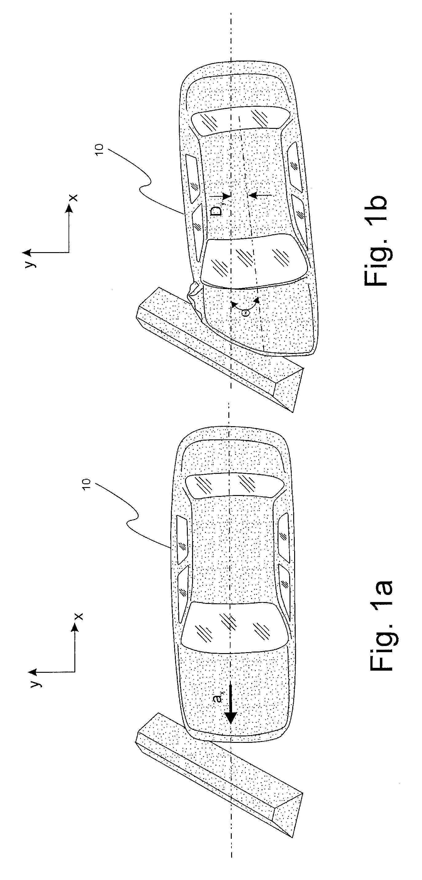
[0009] FIGS. 1a and 1b show the movement of a vehicle before and after an impact barrier test.
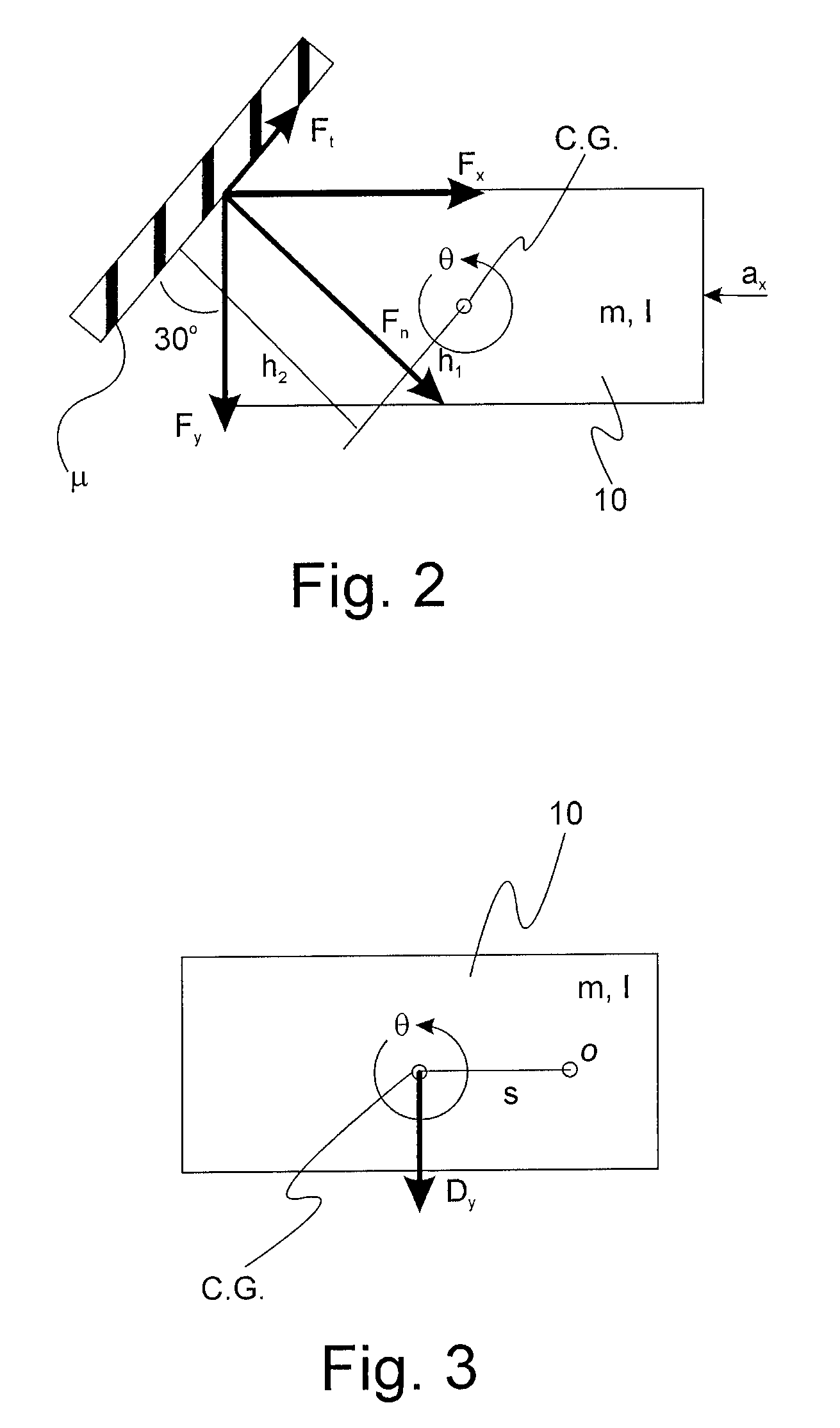
[0010] FIG. 2 shows a model of the forces acting on the vehicle of FIGS. 1a and 1b.
[0011] FIG. 3 shows a model of the movement of the vehicle of FIGS. 1a and 1b.
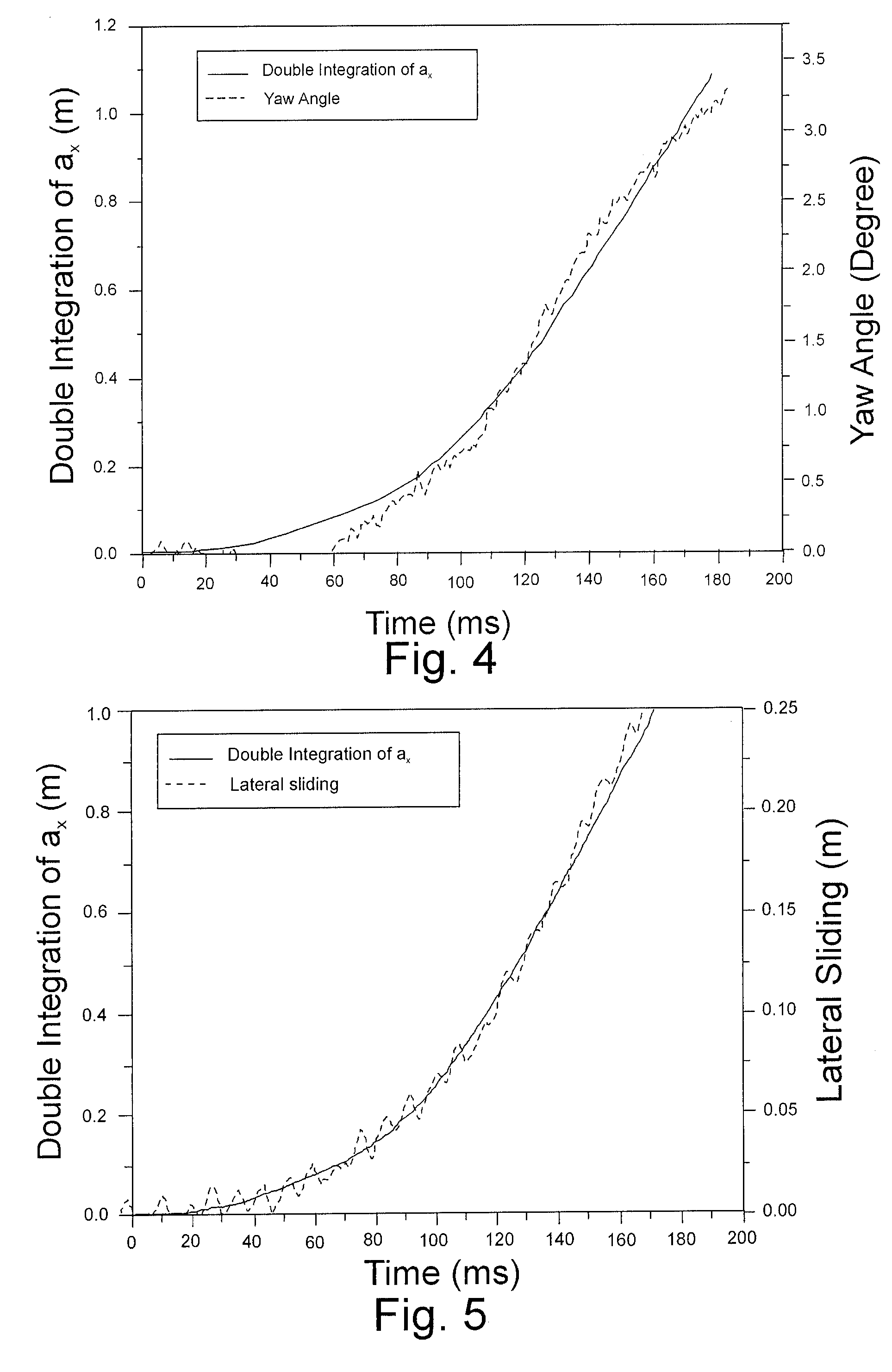
[0012] FIG. 4 shows example data used to determine the validity of derived relationships describing the movement of the vehicle of FIGS. 1a and 1b.
[0013] FIG. 5 shows example data used to determine the validity of derived relationships describing the movement of the vehicle of FIGS. 1a and 1b.
[0014] FIGS. 6a and 6b show models of the movement and the forces acting on a sled buck testing system.
[0015] FIG. 7 shows a plan view of a pivoting arm sled buck testing system in accordance with an embodiment of the invention.
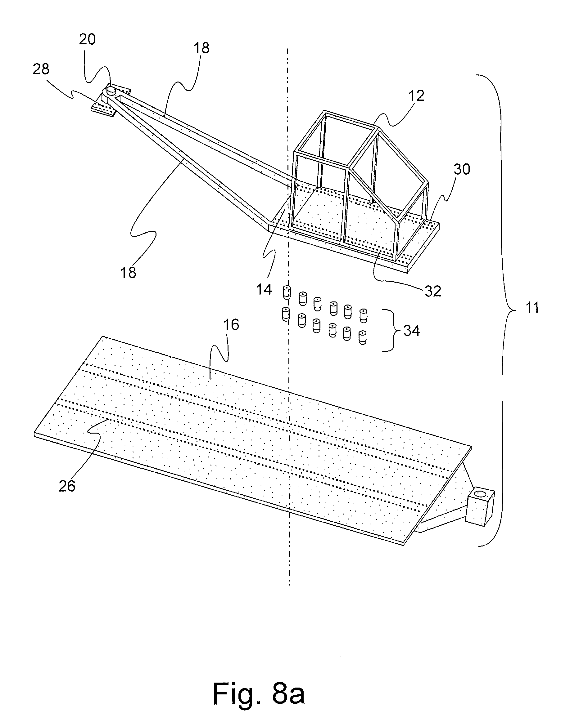
[0016] FIG. 8a shows an exploded perspective view of a the pivoting arm sled buck testing system of FIG. 7.
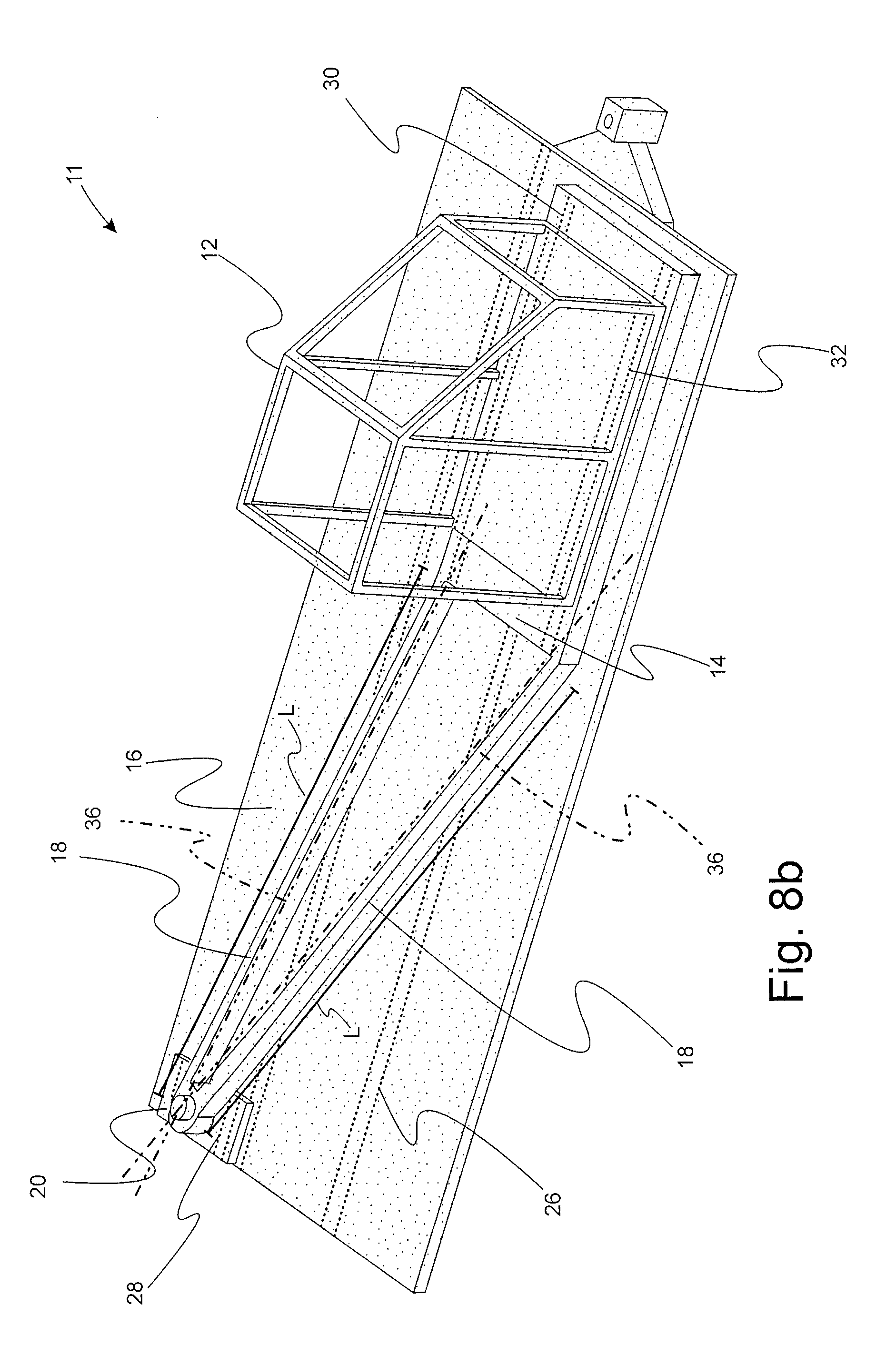
[0017] FIG. 8b shows an assembled perspective view of the pivoting arm sled buck testing system of FIG. 8a.
[0018] FIG. 9 shows a plan view of a curved rail sled buck testing system in accordance with an embodiment of the invention.
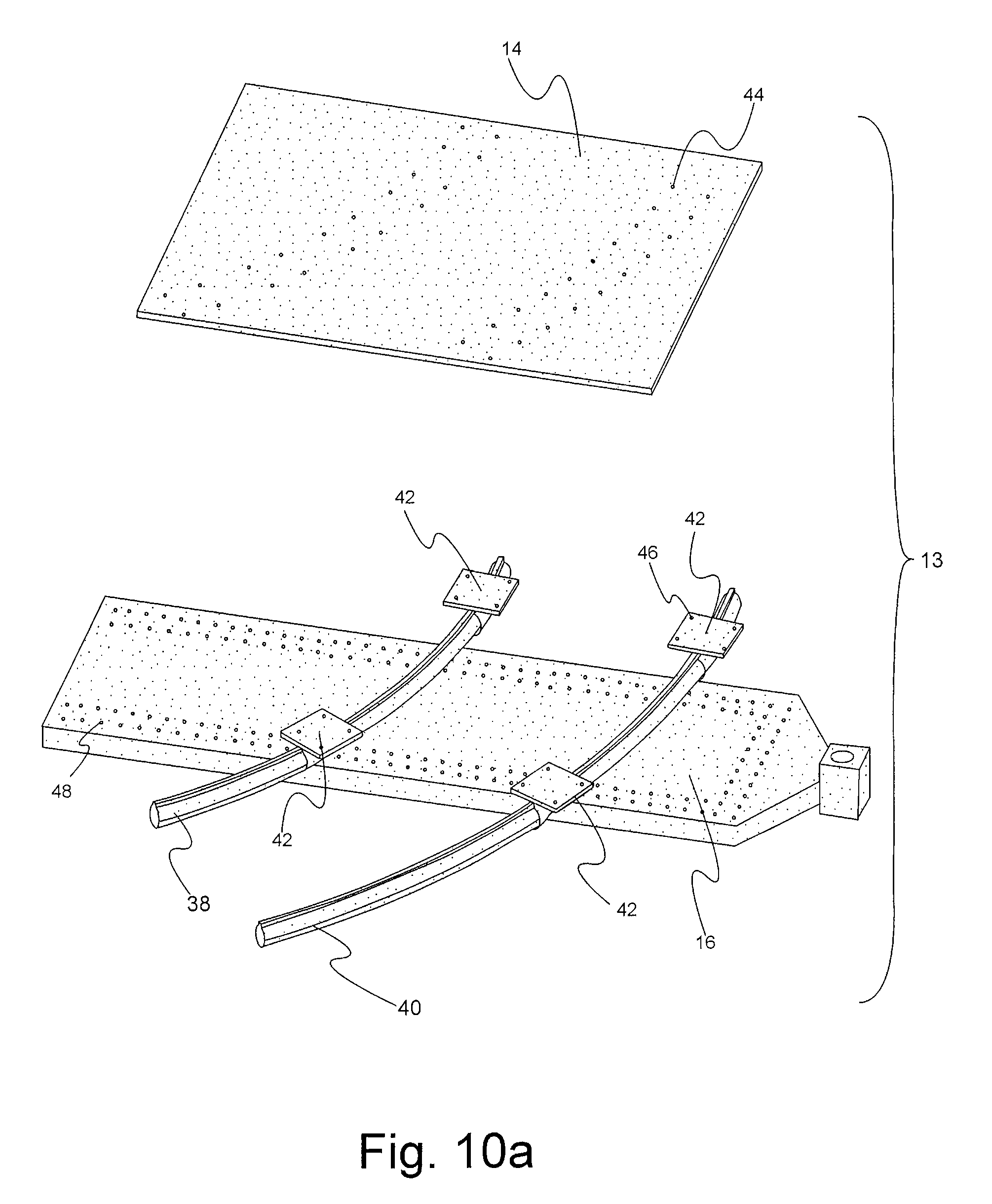
[0019] FIG. 10a shows an exploded perspective view of a portion of the curved rail sled buck testing system of FIG. 9.
[0020] FIG. 10b shows an assembled perspective view of the curved rail sled buck testing system of FIG. 10a.
DETAILED DESCRIPTION
[0021] FIG. 1a shows vehicle 10 experiencing longitudinal acceleration, a.sub.x, in an X-Y plane prior to a 30 degree impact. FIG. 2a shows that, after impact, vehicle 10 experienced lateral movement, D.sub.y, and yaw movement, .theta..
[0022] FIG. 2 shows a rigid body model of vehicle 10, where
C.G.: Center of gravity F.sub.n: Barrier normal force F.sub.t: Barrier friction force F.sub.x: Force component in X direction F.sub.y: Force component in Y direction .mu.: Coefficient of friction a.sub.x: Vehicle longitudinal pulse .theta.: Vehicle yaw angle h.sub.1 & h.sub.2: Moment arm of F.sub.n and F.sub.t with respect to C.G., and m & I: Vehicle 10 mass and moment of inertia. and where
F.sub.x=F.sub.n cos 30.degree.+F.sub.t sin 30.degree. (1)
while
F.sub.t=.mu.F.sub.n (2)
and,
F.sub.x=ma.sub.x,F.sub.y=ma.sub.y. (3)
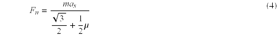
Thus,
[0023] F n = ma x 3 2 + 1 2 .mu. ( 4 ) ##EQU00001##
[0024] The equation of angular motion is given by
F.sub.nh.sub.1-F.sub.th.sub.2=I{umlaut over (.theta.)}. (5)
Substituting (2) and (4) into (5) yields
( h 1 - .mu. h 2 ) ma x 3 2 + 1 2 .mu. = I .theta. . ( 6 ) ##EQU00002##
Rearranging (6) yields
.theta. = ( h 1 - .mu. h 2 ) m ( 3 2 + 1 2 .mu. ) I a x ( 7 ) ##EQU00003##
or
r{umlaut over (.theta.)}=a.sub.x (8)
where
r = ( 3 2 + 1 2 .mu. ) I ( h 1 - .mu. h 2 ) m . ##EQU00004##
Thus, r is a vehicle 10 dependent constant.
[0025] Applying a double integration to (8) yields
.theta. = .intg. .intg. .theta. t t = 1 r .intg. .intg. a x t t . ( 9 ) ##EQU00005##
Equilibrium in the Y direction is given by
F.sub.y=F.sub.n sin 30.degree.-F.sub.t cos 30.degree.. (10)
Substituting (2) and (4) into (10) yields
F y = ( 1 2 - 3 2 .mu. ) ( 3 2 + 1 2 .mu. ) ma x . ( 11 ) ##EQU00006##
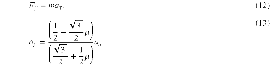
Because
[0026] F y = ma y , ( 12 ) a y = ( 1 2 - 3 2 .mu. ) ( 3 2 + 1 2 .mu. ) a x . ( 13 ) ##EQU00007##
[0027] Applying a double integration to both sides of (13) yields
D.sub.y=.intg..intg.a.sub.ydtdt=C.intg..intg.a.sub.xdtdt (14)
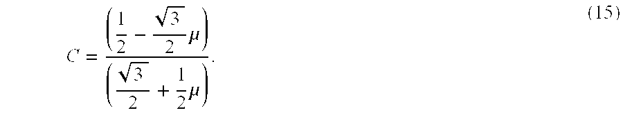
where
C = ( 1 2 - 3 2 .mu. ) ( 3 2 + 1 2 .mu. ) . ( 15 ) ##EQU00008##
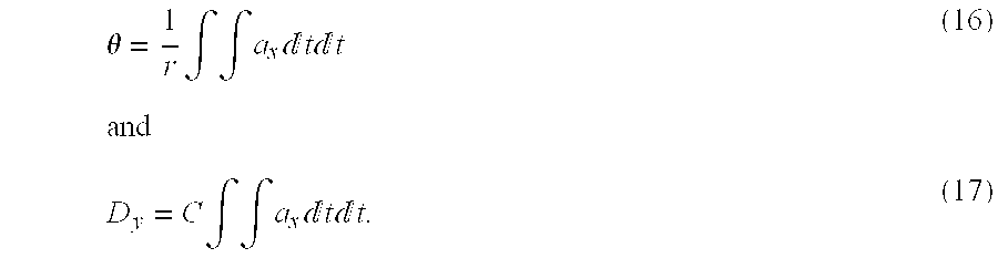
Thus,
[0028] .theta. = 1 r .intg. .intg. a x t t ( 16 ) and D y = C .intg. .intg. a x t t . ( 17 ) ##EQU00009##
[0029] (16) and (17) describe the motion of vehicle 10 in the X-Y plane, e.g., longitudinal deceleration, lateral motion, and yaw, in terms of one independent degree of freedom, e.g., a.sub.x.
[0030] FIG. 3 shows a rigid body model of vehicle 10 using notation as described for FIG. 2 and where [0031] s: Distance between the instantaneous center of rotation, o, and the C.G.
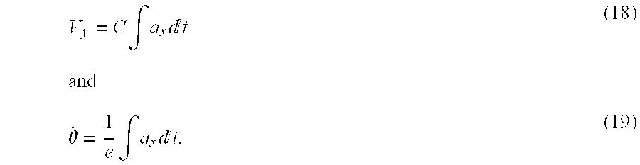
[0032] At the C.G., the lateral velocity and angular velocity can be obtained by
V y = C .intg. a x t ( 18 ) and .theta. . = 1 e .intg. a x t . ( 19 ) ##EQU00010##
At the instantaneous center of rotation, o, 20
V.sub.y=s{dot over (.theta.)}. (20)
Thus,
s=rC. (21)
[0033] Substituting C and r into (21) leads to
s = ( 1 2 - 3 2 .mu. ) I ( h 1 - .mu. h 2 ) m . ( 22 ) ##EQU00011##
[0034] The validity of (16) and (17), as well as the values for r and C, can be determined experimentally by, for example, analyzing barrier vehicle response or structural data.
[0035] FIG. 4 shows a example plot of yaw angle, in degrees, and the double integration of a.sub.x, in meters, versus time, in milliseconds. The match between the two curves validates (16). r is equal to the ratio of the two Y-axis scales.
[0036] FIG. 5 shows a plot of lateral sliding, in meters, and the double integration of a.sub.x, in meters, versus time, in milliseconds. The match between the two curves validates (17). C is equal to the ratio of the two Y-axis scales.
[0037] FIGS. 6a and 6b show models of sled buck 12 and platform 14 (assuming a small .theta.) where
m.sub.s: Mass of sled buck 12 and platform 14 R: Radius of gyration about the C.G. I.sub.o: Moment of inertia about the center of rotation, o, and a.sub.p: Applied acceleration on platform 14.
[0038] The equation of motion about the center of rotation, o, is given by
m.sub.sa.sub.pe=I.sub.o{umlaut over (.theta.)} (23)
where
I.sub.o=m.sub.s(e.sup.2+s.sup.2+R.sup.2) (24)
and the kinematic equation at the C.G. is given by
a.sub.x=a.sub.p-e{umlaut over (.theta.)}. (25)
(23), (24), and (25) yield
a p = ( 1 + e 2 s 2 + R 2 ) a x ( 26 ) ##EQU00012##
[0039] Substituting (26) into (23) yields
a x = s 2 + R 2 e .theta. . ( 27 ) ##EQU00013##
Also,
[0040] a.sub.y=s{umlaut over (.theta.)}, (28)
a.sub.x=r{umlaut over (.theta.)}, (29)
and
a.sub.y=Ca.sub.x. (30)
[0041] With (27), (28) becomes
a y = es s 2 + R 2 a x . ( 31 ) ##EQU00014##
[0042] To simulate impact barrier testing, a.sub.x, a.sub.y, and {umlaut over (.theta.)} have to meet the requirements described in (8) and (30). Therefore,
s 2 + R 2 e = r ( 32 ) and es s 2 + R 2 = C . ( 33 ) ##EQU00015##
[0043] Solving (32) and (33) for e and s yields
e = r 2 C 2 + R 2 r , ( 34 ) s = rC , ( 35 ) and a p = ( 1 + e 2 s 2 + R 2 ) a x . ( 36 ) ##EQU00016##
[0044] An example given by r.apprxeq.15, R.apprxeq.0.5, and C.apprxeq.0.25 yields
s.apprxeq.4.0 m,
e.apprxeq.1.0 m,
and
a.sub.p.apprxeq.1.05a.sub.x.
[0045] FIG. 7 shows a plan view of pivoting arm sled buck testing system 11. System 11 includes sled buck 12, platform 14, and sled carriage 16. Platform 14 is connected to carriage 16 via arms 18 at pivot 20. Pivot 20 is aligned with center of rotation, o.
[0046] Carriage 16, in response to the acceleration pulse, a.sub.p, travels along carriage rails 22 in the direction of carriage axis 24.
[0047] s is the longitudinal distance along axis 24 between center of rotation, o, and center of gravity, C.G. e is the lateral distance between center of rotation, o, and center of gravity, C.G.
[0048] FIG. 8a shows an exploded view of system 11. Pivot 20 is removably attached with carriage 16 via locating holes 26, 28 respectively associated with carriage 16 and pivot 20. Pivot 20 may be bolted or otherwise attached with carriage 16 via locating holes 26, 28. Platform 14 is removably attached with sled buck 12 via locating holes 30, 32 respectively associated with platform 14 and sled buck 12. Sled buck 12 may be bolted or otherwise attached with platform 14 via locating holes 30, 32.
[0049] Rollers 34 attached with platform 14 facilitate movement between platform 14 and carriage 16.
[0050] FIG. 8b shows an assembled view of system 11 of FIG. 8a. Arms 18 each include an arm axis 36. Arm axes 36 intersect at pivot 20. Arms 18 each have a respective length L. In the example of FIG. 8a, the respective lengths, L, of arms 18 are not equal.
[0051] Upon acceleration of carriage 16 by acceleration pulse, a.sub.p, sled buck 12 and platform 14 will move relative to carriage 16. In particular, sled buck 12 and platform 14 will translate relative to carriage 16 as governed by (17) and sled buck 12 and platform 14 will rotate about center of rotation, o, which is aligned with pivot 20, as governed by (16).
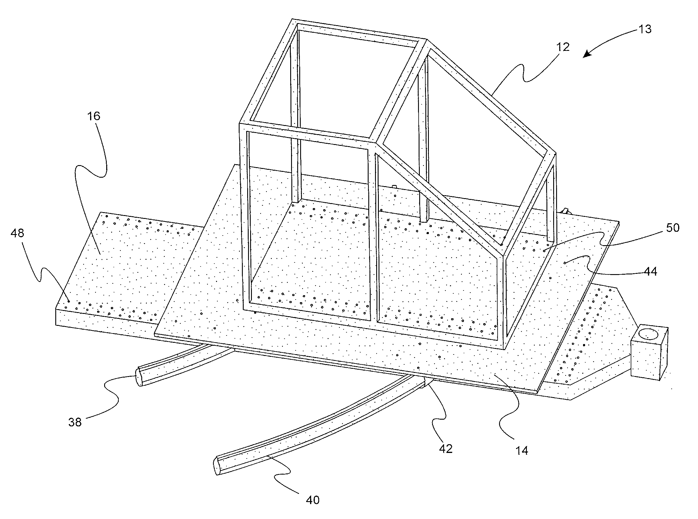
[0052] FIG. 9 shows a plan view of a curved rail sled buck testing system 13. System 13 includes curved rail 38 and curved rail 40. Curved rail 38 has a radius of curvature 42 whose origin is the center of rotation, o. Curved rail 40 has a radius of curvature 44 whose origin is the center of rotation, o. As described above, carriage 16 travels along carriage rails 22 in the direction of carriage axis 24 in response to an acceleration pulse, a.sub.p.
[0053] FIG. 10a shows an exploded view of a portion of system 13. Sliders 42 attached with platform 14 and rails 38, 40, respectively, facilitate the movement of platform 14 relative to carriage 16. Platform 14 is removably attached with sliders 42, via locating holes 44, 46 respectively associated with platform 14 and sliders 42. Rails 38, 40 are removably attached with carriage 16 via locating holes 48. Rails 38, 40 may be bolted or otherwise connected with carriage 16 via locating holes 48.
[0054] FIG. 10b shows an assembly view of system 13. Sled buck 12 includes locating holes 50 for locating sled buck 12 relative to platform 14.
[0055] Upon acceleration of carriage 16 by acceleration pulse, a.sub.p, sled buck 12 and platform 14 will move relative to carriage 16. In particular, sled buck 12 and platform 14 will translate relative to carriage 16 as governed by (17) and sled buck 12 and platform 14 will rotate about center of rotation, o, relative to carriage 16 as governed by (16).
[0056] While embodiments of the invention have been illustrated and described, it is not intended that these embodiments illustrate and describe all possible forms of the invention. Rather, the words used in the specification are words of description rather than limitation, and it is understood that various changes may be made without departing from the spirit and scope of the invention.
* * * * *
D00000
D00001
D00002
D00003
D00004
D00005
D00006
D00007
D00008
D00009


XML
uspto.report is an independent third-party trademark research tool that is not affiliated, endorsed, or sponsored by the United States Patent and Trademark Office (USPTO) or any other governmental organization. The information provided by uspto.report is based on publicly available data at the time of writing and is intended for informational purposes only.
While we strive to provide accurate and up-to-date information, we do not guarantee the accuracy, completeness, reliability, or suitability of the information displayed on this site. The use of this site is at your own risk. Any reliance you place on such information is therefore strictly at your own risk.
All official trademark data, including owner information, should be verified by visiting the official USPTO website at www.uspto.gov. This site is not intended to replace professional legal advice and should not be used as a substitute for consulting with a legal professional who is knowledgeable about trademark law.