Self-transforming structures
Tibbits , et al. Dec
U.S. patent number 10,513,089 [Application Number 14/879,035] was granted by the patent office on 2019-12-24 for self-transforming structures. This patent grant is currently assigned to Carbitex, Inc., Massachusetts Institute of Technology. The grantee listed for this patent is Carbitex, Inc., Massachusetts Institute of Technology. Invention is credited to Junus Ali Khan, Athina Papadopoulou, Skylar J. E. Tibbits.
View All Diagrams
| United States Patent | 10,513,089 |
| Tibbits , et al. | December 24, 2019 |
Self-transforming structures
Abstract
A self-transforming structure is formed from a flexible, fibrous composite having a weave pattern of fibers woven at intersecting angles, the weave pattern having a boundary and one or more axes for the fibers, and an added material coupled to the flexible, fibrous composite to form a structure, wherein the flexible, fibrous composite and the added material have different expansion or contraction rates in response to an external stimulus to cause the structure to self-transform, and wherein the added material has a grain pattern oriented relative the weave pattern of the flexible, fibrous composite. Applications of the self-transforming structures include aviation, automotive, apparel/footwear, furniture, and building materials. One particular example is for providing adaptive control of fluid flow, such as in a jet engine air inlet.
| Inventors: | Tibbits; Skylar J. E. (Boston, MA), Papadopoulou; Athina (Cambridge, MA), Khan; Junus Ali (Kennewick, WA) | ||||||||||
|---|---|---|---|---|---|---|---|---|---|---|---|
| Applicant: |
|
||||||||||
| Assignee: | Massachusetts Institute of
Technology (Cambridge, MA) Carbitex, Inc. (Kennewick, WA) |
||||||||||
| Family ID: | 54542491 | ||||||||||
| Appl. No.: | 14/879,035 | ||||||||||
| Filed: | October 8, 2015 |
Prior Publication Data
| Document Identifier | Publication Date | |
|---|---|---|
| US 20160101594 A1 | Apr 14, 2016 | |
Related U.S. Patent Documents
| Application Number | Filing Date | Patent Number | Issue Date | ||
|---|---|---|---|---|---|
| 62061197 | Oct 8, 2014 | ||||
| Current U.S. Class: | 1/1 |
| Current CPC Class: | B32B 3/16 (20130101); B32B 5/18 (20130101); B32B 27/06 (20130101); B32B 5/024 (20130101); B32B 7/02 (20130101); B32B 5/02 (20130101); B32B 27/12 (20130101); B32B 27/34 (20130101); Y10T 428/24942 (20150115); B32B 2605/18 (20130101); B33Y 80/00 (20141201); Y10T 428/24802 (20150115); B32B 2262/106 (20130101); B32B 2605/08 (20130101); B32B 2437/02 (20130101); B32B 2437/00 (20130101); B32B 2307/518 (20130101); B32B 2419/00 (20130101); B32B 2307/52 (20130101); B32B 2479/00 (20130101) |
| Current International Class: | B32B 7/02 (20190101); B32B 5/02 (20060101); B32B 5/18 (20060101); B32B 27/34 (20060101); B32B 3/16 (20060101); B32B 27/12 (20060101); B32B 27/06 (20060101); B33Y 80/00 (20150101) |
References Cited [Referenced By]
U.S. Patent Documents
| 3081514 | March 1963 | Griswold |
| 3391048 | July 1968 | Dyer |
| 3468748 | September 1969 | Bassett |
| 4205152 | May 1980 | Mizuguchi et al. |
| 4290170 | September 1981 | Brookstein |
| 4575330 | March 1986 | Hull |
| 4674580 | June 1987 | Schuh |
| 4735418 | April 1988 | Engel |
| 6012494 | January 2000 | Balazs |
| 6264199 | July 2001 | Schaedel |
| 6569373 | May 2003 | Napadensky |
| 7007370 | March 2006 | Gracias et al. |
| 7225045 | May 2007 | Gothait et al. |
| 7300619 | November 2007 | Napadensky et al. |
| 7500846 | March 2009 | Eshed et al. |
| 7851122 | December 2010 | Napadensky |
| 8475074 | July 2013 | Henry |
| 8652602 | February 2014 | Dolla |
| 8992183 | March 2015 | Perich et al. |
| 9079337 | July 2015 | Lipton et al. |
| 9487378 | November 2016 | MacCurdy et al. |
| 9723866 | August 2017 | Lipson et al. |
| 9993104 | June 2018 | Lipton et al. |
| 10118339 | November 2018 | Lipton et al. |
| 10132931 | November 2018 | MacCurdy et al. |
| 10259161 | April 2019 | Lipton et al. |
| 2002/0043950 | April 2002 | Yim et al. |
| 2002/0104973 | August 2002 | Kerekes |
| 2002/0116847 | August 2002 | Yen |
| 2003/0090034 | May 2003 | Mulhaupt et al. |
| 2005/0227560 | October 2005 | Allred, III |
| 2007/0036964 | February 2007 | Rosenberger et al. |
| 2008/0027199 | January 2008 | Mazurek et al. |
| 2008/0066393 | March 2008 | Sorensen |
| 2008/0109103 | May 2008 | Gershenfeld et al. |
| 2008/0269420 | October 2008 | Tong |
| 2008/0282527 | November 2008 | Beck et al. |
| 2009/0233067 | September 2009 | Doornheim et al. |
| 2010/0168439 | July 2010 | Olson |
| 2011/0285052 | November 2011 | Wigand et al. |
| 2012/0068378 | March 2012 | Swanson et al. |
| 2012/0133080 | May 2012 | Moussa et al. |
| 2012/0308805 | December 2012 | Sella |
| 2013/0040091 | February 2013 | Dikovsky et al. |
| 2013/0073068 | March 2013 | Napadensky |
| 2013/0089642 | April 2013 | Lipson et al. |
| 2013/0249981 | September 2013 | Nakagawa |
| 2014/0013962 | January 2014 | Lipton et al. |
| 2014/0050811 | February 2014 | Lipton et al. |
| 2015/0014881 | January 2015 | Elsey |
| 2015/0158244 | June 2015 | Tibbits et al. |
| 2015/0174885 | June 2015 | Khan |
| 2016/0023403 | January 2016 | Ramos |
| 2016/0067918 | March 2016 | Milar |
| 2016/0214321 | July 2016 | Tow et al. |
| 2017/0042034 | February 2017 | MacCurdy et al. |
| 2017/0057704 | March 2017 | Li et al. |
| 2017/0120535 | May 2017 | MacCurdy et al. |
| 2017/0326785 | November 2017 | MacCurdy et al. |
| 2018/0156204 | June 2018 | Lipton |
| 2018/0194106 | July 2018 | Tibbits et al. |
| 2018/0195213 | July 2018 | Tibbits et al. |
| 2018/0281295 | October 2018 | Tibbits et al. |
| 2018/0311833 | November 2018 | Lipton et al. |
| 20 2008 015 143 | Mar 2009 | DE | |||
| 2455167 | Jun 2009 | GB | |||
| WO 00/69747 | Nov 2000 | WO | |||
| 01/78968 | Oct 2001 | WO | |||
| 2014014892 | Jan 2014 | WO | |||
| WO 2015/084422 | Jun 2015 | WO | |||
| WO 2015/139095 | Sep 2015 | WO | |||
| WO 2016/057853 | Apr 2016 | WO | |||
| WO 2017/079475 | May 2017 | WO | |||
| 2018/187514 | Oct 2018 | WO | |||
Other References
|
"Muscle Flber Organization" acquired from https://oli.cm.edu/jcourse/workbook/activity/page?context=b880ee6c80020ca- 60176cda86237b123 on Mar. 18, 2018. cited by examiner . "Skeletal Muscle Organ Anatomy" acquired from https://oli.cm.edu/jcourse/workbook/activity/page?context=b880ee6b80020ca- 601351c786c5dfea8 on Mar. 18, 2018. cited by examiner . International Search Report and Written Opinion for International Application No. PCT/US2016/060386, titled: "Additive Manufacturing of a Structure by Deposition of Solidifying and Non-Solidifying Materials;" dated Mar. 27, 2017. cited by applicant . International Preliminary Report on Patentability and Written Opinion for International Application No. PCT/US2015/054786, titled: "Self-Transforming Structures;" dated Apr. 11, 2017. cited by applicant . International Preliminary Report on Patentability for International Application No. PCT/US2014/018373, titled: "Object of Additive Manufacture With Encoded Predicted Shape Change," dated Jun. 7, 2016. cited by applicant . Invitation to Pay Additional Fees and Partial International Search for International Application No. PCT/US2016/060386, titled: "Actuatable Assemblies Fabricatable by Deposition of Solidifying and Non-Solidifying Materials," dated Feb. 3, 2017. cited by applicant . 3D Printing (Photolithography), MRSEC Education Group, University of Wisconsin--Madison. Accesed: Nov. 23, 2016. cited by applicant . About Additive Manufacturing, Additive Manufacturing Research Group, Loughborough University, copyright 1016, http://www.lboro.ac.uk!research/amrg/about/the7categoriesofadditivemanufa- cturing/. cited by applicant . Aguilera, E., et al., "3D Printing of Electro Mechanical Systems," 24th International SFF Symposium--An Additive Manufacturing Conference, SFF 2013, pp. 950-961 (2013). cited by applicant . Ahn, J-H., et al., "Heterogeneous Three-Dimensional Electronics by Use of Printed Semiconductor Nanomaterial," Science, 314: 1754-1757 (2006). cited by applicant . Akhavan, V., et al., "Reacting Thick-Film Copper Conductive Inks with Photonic Curing," 5 pages (2013). cited by applicant . Altan, T., et al., "Manufacturing of Dies and Molds," 19 pages (2001). cited by applicant . Bailey, S.A., et al., "Biomimetic Robotic Mechanisms via Shape Deposition Manufacturing," pp. 1-8 (2000). cited by applicant . Bartlett, Nicholas W., et al., "A 3D-printed, functionally graded soft robot powered by combustion," Science, 349(6244): 161-166 (Jul. 10, 2015). cited by applicant . Bendsoe, M.P. and Kikuchi, N., "Generating Optimal Topologies in Structural Desing Using a Homogenization Method," Comp. Meth. App. Mech. Eng., 71: 197-224 (1988). cited by applicant . Berman, B., "3-D Printing: The New Industrial Revolution," Business Horizons, 55: 155-162 (2012). cited by applicant . Bhargava, K. et al., "Discrete Elements for 3D Microfluidics," PNAS, 111(42): 15013-15018 (2014). cited by applicant . Bicchi, A. and Tonietti, G., "Fast and `Soft-Arm` Tactics," IEEE Robotics & Automation Magazine, 22-33 (2004). cited by applicant . Blakely, Andrew M., "Bio-Pick, Place, and Perfuse: A New Instrument for 3D Tissue Engineerin " Tissue Engineering: Part C, vol. 00, No. 00, pp. 1-10 (2015). cited by applicant . Borghino, D., "Voxel8 Paves the Way for 3D-Printed Electronics," Accessed at www.gizmag.com pp. 1-6 (Jan. 14, 2015). cited by applicant . Bruyas, A., et al., "Combining Multi-Material Rapid Prototyping and Pseudo-Rigid Body Modeling for a New Compliant Mechanism," 2014 IEEE International Conference on Robotics & Automation (ICRA), pp. 3390-3396 (2014). cited by applicant . Cali, J., et al., "3D-Printing of Non-Assembly, Articulated Models," ACM Trans. Graph., Article No. 130, 31(6): 1-8 (2012). cited by applicant . Cantatore, E., "Applications of Organic and Printed Electronics, A Technology-Enabled Revolution," Springer Publishers, ISBN No. 978-1-4614-3159-6, pp. 1-187 (2013). cited by applicant . Cheney, N., et al., "Unshackling Evolution," SIGEVOlution, 7(1): 11-23 (2013). cited by applicant . Christenson, K.K., et al., "Direct Printing of Circuit Boards Using Aerosol Jet.RTM.," Tech. Prog. Proc., pp. 433-436 (2011). cited by applicant . Church, K., et al., "Commercial Applications and Review for Direct Write Technologies," Mat. Res. Soc. Symp. Proc., 624: 3-8 (2000). cited by applicant . Comber, D.B., et al., "Design, Additive Manufacture, and Control of a Pneumatic MR-Compatible Needle Driver," IEEE Trans. Rob., 1-12 (2015). cited by applicant . Coros, S., et al., "Computational Design of Mechanical Characters," 12 pages (2013). cited by applicant . De Laurentis, K.J., et al., "Procedure for Rapid Fabrication of Non-Assembly Mechanisms with Embedded Components," Proceedsing of DETC'02: ASME 2002 Design Engineering Technical Conferences and Computers and Information in Engineering Conference, pp. 1-7 (2002). cited by applicant . Derby, B., "Inkjet Printing of Functional and Structural Materials: Fluid Property Requirements, Feature Stability, and Resolution," Annu. Rev. Mater. Res., 40: 395-414 (2010). cited by applicant . Dimas, L.S., et al., "Tough Composites Inspired by Mineralized Natural Materials: Computation, 3D Printing, and Testing," Adv. Funct. Mater., 23(36): 1-10 (2013). cited by applicant . Doubrovski, E.L., et al. ,"Voxel-Based Fabrication Through Material Property Mapping: A Design Method for Bitmap Printing," Computer-Aided Design, 60: 3-13 (2015). cited by applicant . Dutta, D., et al., "Layered Manufacturing: Current Status and Future Trends," Trans. ASME, 1:60-71 (Mar. 2001). cited by applicant . Eaton, M., et al., "The Modellilng, Prediction, and Experimental Evaluation of Gear Pump Meshing Pressures with Particular Reference to Aero-Engine Fuel Pumps," Proc. IMechE, 220 (Part 1): 365-379 (2006). cited by applicant . Espalin, D., et al., "3D Printing Multifunctionality: Structures with Elements," Int. J. Adv. Manuf. Technol., 72: 963-978 (2014). cited by applicant . Ferry, P.W., et al., "A Review on Stereolithography and Its Applications in Biomedical Engineering," Biomat., 31: 6121-6130 (2010). cited by applicant . Fuller, S.B., et al., "Ink-Jet Printed Nanoparticle Microelectromechanical Systems," J. Microelec. Sys., 11(1): 54-60 (2002). cited by applicant . Gong, H., et al., "High Density 3D Printed Microfluidic Valves, Pumps, and Multiplexers, Lab on a Chip" Royal Society of Chemistry, 9 pages (2016). cited by applicant . Grunewald, S., "Nano Dimension Unveils the DragonFly 2020, World's First Desktop Electronic 3D Printer," Downloaded from https://3DPrint.com, The Voice of 3D Printing Technologies, pp. 1-5 (Nov. 18, 2015). cited by applicant . Grzesiak, A., et al., "The Bionic Handling Assistant: A Success Story of Additive Manufacturing," Assemb. Autom., 31(4): 329-333 (2011). cited by applicant . Hawkes et al. Programmable matter by folding, PNAS, vol. 107(28): 12441-12445 (2010). cited by applicant . Hiller, J. and Lipson, H., "Automatic Design and Manufacture of Soft Robots," IEEE Trans. Rob., 28(2): 457-466 (2012). cited by applicant . Hiller, J. and Lipson, H., "Methods of Parallel Voxel Manipulation for 3D Digital Printing," pp. 200-211 (2007). cited by applicant . Hiller, J. and Lipson, H., "Tunable Digital Material Properties for 3D Voxel Printers," Rapid Prototyping Journal, 16(4): 241-247 (2009). cited by applicant . Hiller, J.D., et al., "Microbricks for Three-Dimensional Reconfigurable Modular Microsystems," J. Microelec. Sys., 20(5): 1089-1097 (2011). cited by applicant . Huber, C., et al., 3D Print of Polymer Bonded Rare-Earth Magnets, and 3D Magnetic Field Scanning with an End-User 3D Printer, Applied Physics Letters, 109: 162401-1 162401-4 (2016). cited by applicant . Ionov, L., "Soft Microorigami: self-folding polymer films," Soft Matter, 7: 6786 (Published online May 24, 2011). cited by applicant . Jeffrey, C., "V-One Conductive Ink Printer Aims to Short-Circuit Electronic Prototyping," accessed on www.gizmag.com pp. 1-6 (Feb. 10, 2015). cited by applicant . Jeong, K-U. et al., "Three-dimensional actuators transformed from the programmed two-dimensional structures via bending, twisting and folding mechanisms," Journal of Materials Chemistry, 21: 6824-6830 (2011). cited by applicant . Kang, H., et al., "Direct Intense Pulsed Light Sintering of Inkjet-Printed Copper Oxide Layers within Six Milliseconds," ACS Appl. Mater. Interfaces, 6:1682-1687 (2014). cited by applicant . Kolesky, D.B., et al. ,"3D Bioprinting of Vascularized, Heterogeneous Cell-Laden Tissue Constructs," Adv. Mater., 26:3124-3130 (2014). cited by applicant . Kong, Y.L., et al., "3D Printed Quantum Dot Light-Emitting Diodes," Nano. Lett., 14:7017-7023 (2014). cited by applicant . Knuth, J.P., et al., "Progress in Additive Manufacturing and Rapid Prototyping," Annals CIRP, 47(2): 525-540 (1998). cited by applicant . Kuehn, T. and Rieffel, J., "Automatically Designing and Printing 3-D Objects with EvoFab 0.2," Artificial Life, 13: 372-378 (2012). cited by applicant . Laschi, C., et al., "Soft Robot Arm Inspired by the Octopus," Adv. Rob., 26: 709-727 (2012). cited by applicant . Li, B., et al., "Robust Direct-Write Dispensing Tool and Solutions for Micro/Meso-Scale Manufacturing and Packaging," ASME Proceedings of the 2007 International Maufacturing Science and Engineering Conference, pp. 1-7 (2007). cited by applicant . Li, X., "Embedded Sensors in Layered Manufacturing," Dissertation submitted to Stanford University, pp. 1-152 (Jun. 2001). cited by applicant . Lin, H.-T., et al., "GoQBot: A Caterpillar-Inspired Soft-Bodied Rolling Robot," Bioinsp. Biomim., 6: 1-14 (2011). cited by applicant . Lipson, H., "Challenges and Opportunities for Design, Simulation, and Fabrication of Soft Robots," Soft Robotics, 1(1): 21-27 (2014). cited by applicant . Lipson, H., and Kurman, M., "Factory@Home--The Emerging Economy of Personal Manufacturing," One of a series of Occasional Papers in Science and Technology Policy, pp. 1-103 (Dec. 2010). cited by applicant . Lipton, J. et al., "Fab@Home Model 3: A More Robust, Cost Effective and Accessible Open Hardware Fabrication Platform," 125-135 (2012). cited by applicant . Louis-Rosenberg, J., "Drowning in Triangle Soup: the Quest for a Better 3-D Printing File Format," XRDS, 22(3): 58-62 (2016). cited by applicant . MacCurdy, R., et al., "Bitblox: A Printable Digital Material for Electromechanical Machines," Int'l J. Robotics Res., 33(10), 1342-1360 (2014). cited by applicant . MacCurdy, R., et al., "Printable Hydraulics: A Method for Fabricating Robots by 3D Co-Printing Solids and Liquids," 2016 IEEE International Conference on Robotics and Automation (ICRA), pp. 1-8 (2016). cited by applicant . MacCurdy, R., et al., "Printable Programmable Viscoelastic Materials for Robots," IEEE/RSJ International Conference on Intelligent Robots and Systems (IROS), pp. 1-8 (2016). cited by applicant . MacDonald, E., et al., "3D Printing for the Rapid Prototyping of Structural Electronics," IEEE, 2:234-242 (2014). cited by applicant . Macdonald, N.P., et al., "Assessment of Biocompatibility of 3D Printed Photopolymers Using Zebrafish Embryo Toxicity Assays," Royal Society of Chemistry--Lab on a chip, 16: 291-297 (2016). cited by applicant . Mack, E., "Beyond 3D Printers and the Coming of the Home Electronics Factory," www.gizmag.com, pp. 1-5 (Oct. 22, 2014). cited by applicant . Malone, E., and Lipson, H., "Multi-Material Freeform Fabrication of Active Systems," Proceedings of the 9.sup.th Biennial ASME Conference on Engineering Systems Design and Analysis, pp. 1-9, (2008). cited by applicant . Mannoor, M.S., et al., "3D Printed Bionic Ears," Nano. Lett., 13: 2634-2639 (2013). cited by applicant . Mao, Y., et al., "Scientific Reports: Sequential Self-Folding Structures by 3D Printed Digital Shape Memory Polymers," Nature, pp. 1-12 (2015). cited by applicant . Marchese, A.D., et al., "A Recipe for Soft Fluidic Elastomer Robots," Soft Robotics, 2(1): 7-25 (2015). cited by applicant . Mehta, A., et al., "Cogeneration of Mechanical, Electrical, and Software Design for Printable Robots from Structural Specifications," Int. Rob. Sys.: 2892-2897 (2014). cited by applicant . Mehta, A., et al., "Integrated Codesign of Printable Robots," J. Mech. Rob., 7: 1-10 (2015). cited by applicant . Meisel, N.A., et al, "A Procedure for Creating Actuated Joints via Embedding Shape Memory Alloys in Polyjet 3D Printing," J. Intel. Mat. Sys. Struct., pp. 1-15 (2014). cited by applicant . Melchels, F. P.W., et al., "A review on stereolithography and its applications in biomedical engineering," Biomaterials, 31:6121-6130 (2010). cited by applicant . Merz, R, "Shape Deposition Manufacturing," Proceedings of the Solid Freeform Fabrication Symposium, The University of Texas at Austin, pp. 1-7 (1994). cited by applicant . Merz, R, et al., Dissertation entitled "Shape Deposition Manufacturing," pp. 1-190 (1994). cited by applicant . Mironov, V., et al., "Organ Printing: Computer-Aided Jet-Based 3D Tissue Engineering," Trends Biotech., 21(4):157-161 (2003). cited by applicant . Morin, S.A., et al., "Using Click-e-Bricks to Make 3D Elastomeric Structures," Adv. Mater., 26: 5991-5999 (2014). cited by applicant . Mueller, S., et at , "faBrickation: Fast 3D Printing of Functional Objects by Integrating Construction Kit Building Blocks," Session: 3D Printing and Fabrication, 3827-3834 (2014). cited by applicant . Mueller, S., et al., "Mechanical Properties of Parts Fabricated with Inkjet 3D Printing Through Efficient Experimental Design," Materials and Design, 86:902-912 (2015). cited by applicant . Murphy, S.V. and Atala, A., "3D Bioprinting of Tissues and Organs," Nat. Biotech., 32(8):773-785 (2014). cited by applicant . Murray, C., "Smart Actuator Propels Hydraulic `Beast of Burden`", Design News [online], Jun. 4, 2015 [retrieved Oct. 21, 2016]. Retrieved from the Internet URL: http://www.designnews.com/document.asp?doc_id=277754. cited by applicant . O'Donnell, J., et al., "A Review on Electromechanical Devices Fabricated by Additive Manufacturing," J. of Manufacturing Science and Engineering, pp. 1-45 (2015). cited by applicant . Palmer, J.A., et al., "Realizing 3-D Interconnected Direct Write Electronics within Smart Stereolithography Structures," Proceedings of IMECE2005-2005 ASME International Mechanical Engineering Congress and Exposition, pp. 1-7 (2005). cited by applicant . Park, S., et al. ,"Self-Assembly of Mesoscopic Metal-Polymer Amphiphiles," Science, 303: 348-351 (2004). cited by applicant . Peele, B.N., et al., "3D Printing Antagonistic Systems of Artificial Muscle Using Projection Stereolithography," Bioinspir. Biomim., 10:1-8 (2015). cited by applicant . Popescu, G. A., et al., "Digital Materials for Digital Printing," Soc. Imaging Sci. Tech., pp. 58-61 (2006). cited by applicant . Popescu, G.A., "Digital Materials for Digital Fabrication," Thesis submitted to Massachusetts Institute of Technology, pp. 1-53 (Aug. 20, 2007). cited by applicant . Proto3000: "3D Printed Snow Globe by Proto3000--Thingiverse," Retrieved from the internet: http://www.thingiverse.com/thing:225572, Retrieved on: Jan. 10, 2017. cited by applicant . Rost, A., and Schadle, S., "The SLS-Generated Soft Robotic Hand--An Integrated Approach Using Additive Manufacturing and Reinforcement Learning," IEEE: 215-220 (2013). cited by applicant . Rus, D. and Tolley, M.T., "Design, Fabrication and Control of Soft Robots," Nature, 521: 467-475 (2015). cited by applicant . Russo, A., et al., "Pen-On-Paper Flexible Electronics," Adv. Mater., 23: 3426-3430 (2011). cited by applicant . Saari, M., et al., "Fiber Encapsulation Additive Manufacturing: An Enabling Technology for 3D Printing of Electromechanical Devices and Robotic Components," 3D Printing, 2(1):32-39 (2015). cited by applicant . Safari, A., et al., "Solid Freeform Fabrication of Piezoelectric Sensors and Actuators," J. Mat. Sci., 41: 177-198 (2006). cited by applicant . Saleh, E., el al., "3D Inkjet-Printed UV-Curable Inks for Multi-Functional Electromagnetic Applications," Proceedings of ISFA2014, pp. 1-5 (2014). cited by applicant . Sangani, K., "How to . . . Print Gadgets," Engineering & Technology, pp. 58-60 (2013). cited by applicant . Sharmis Passions, "Eggless Chocolate Cake--Moist Chocolate Cake Recipe (No eggs No butter)," http://www.sharmispassions.com/201 0/03/simple-moi stchocolate-cakewith-no-eggs. html, pp. 1-37 (posted Mar. 27, 2010). cited by applicant . Sitthi-Amorn, P., et al., "MultiFab: A Machine Vision Assisted Platform for Multi-Material 3D Printing," ACM lransactions on Graphics, Article No. 129, 34(4): 1-11 (2015). cited by applicant . Slightam, J.E. and Gervasi, V.R., "Novel Integrated Fluid-Power Actuators for Functional End-Use Components and Systems via Selective Laser Sintering Nylon 12," 23rd Ann Int Solid Freeform Fabrication Symp: pp. 197-211 (2012). cited by applicant . Slotwinski, J.A., "Materials Standards for Additive Manufacturing," National Institute of Standards and Technology (NIST), PDES, Inc. Workshop (Mar. 14, 2013). cited by applicant . Snyder, T.J., et al., "3D Systems' Technology Overview and New Applications in Manufacturing, Engineering, Science, and Education," Mary Ann Liehert, Inc., 1(3):169-176 (2014). cited by applicant . Takatsu, H., et al., "Stress Analysis Method of U-Shaped Bellows and Its Experimental Verification," Fusion Eng. & Des., 22: 239-250 (1993). cited by applicant . Tanaka, M., "Fatigue Life Estimation of Bellows Based on Elastic-Plastic Calculations," Int. J. Pres. Ves. & Piping, 2: 51-68 (1974). cited by applicant . Thomaszewski, B., et al., "Computational Design of Linkage-Based Characters," 9 pages (2014). cited by applicant . Thryft, Ann R., "3D Printing Now Good Enough for Final & Spare Car Parts," downloaded from www.designnews.com, 3 pages, (Jul. 22, 2016). cited by applicant . Tibbets, S. and Cheung, K., "Programmable Materials for Architectural Assembly and Automation," Assembly Automation, 32(3): 216-225 (2012). cited by applicant . Tolley, M.T., et al,"A Resilient, Untethered Soft Robot," Soft Robotics, 1(3): 213-223 (2014). cited by applicant . Torrisi, F., et al., "Inkjet-Printed Graphene Electronics," Am. Chem. Soc., 6(4): 2992-3006 (2012). cited by applicant . Tumbleston, J.R., et al., "Continuous Liquid Interface Production of 3D Objects," Research Reports, 347(6228): 1349-1353 (2015). cited by applicant . Tunisianswife, Easy Chocolate Bundt Cake Glaze (allrecipies.com accessed Jun. 6, 2016) http:/ /all recipes. com/recipe/1 00335/easy -choco late-bu ndt -cake-glaze/. cited by applicant . Ultem.RTM./PEI (Polyetherimide): Aetna Plastics, Accessed: Jun. 1, 2016. cited by applicant . Waheed, S., "3D Printed Microfluidic Devices: Enablers and Barriers," Royal Society of Chemistry, Lab on a chip, 16: 1993-2013 (2016). cited by applicant . Walker, S.B. and Lewis, J.A., "Reactive Silver Inks for Patterning High-Conductivity Features at Mild Temperatures," Am. Chem. Soc., 134: 1419-1421 (2012). cited by applicant . Wang, L., et al., "Robotic Folding of 2D and 3D Structures from a Ribbon," IEEE International Conference on Robotics and Automation (ICRA), pp. 3655-3660 (2016). cited by applicant . Weiss, L., et al. ,"Shape Deposition Manufacturing of Wearable Computers," pp. 31-38 (1996). cited by applicant . Weiss, L.E., et al., "Shape Deposition Manufacturing of Heterogeneous Structures," J. Mann. Sys., 16(4): 239-248 (1997). cited by applicant . Whitney, J. P., et al., "A Low-Friction Passive Fluid Transmission and Fluid-Tendon Soft Actuator," 8 pages (2014). cited by applicant . Willis, K.D.D., et al., "Printed Optics: 3D Printing of Embedded Optical Elements for Interactive Devices," UIST'12, pp. 589-598 (Oct. 2012). cited by applicant . Wu, S-Y., et al., "3D-Printed Microelectronics for Integrated Circuitry and Passive Wireless Sensors," Microsystems & Nanoengineering, 1:1-9 (2015). cited by applicant . Xie, T., "Tunable polymer multi-shape memory effect," Nature Letters, 464: 267-270 (2010). cited by applicant . Xu, S., et al.,"Soft Microfluidic Assemblies of Sensors, Circuits, and Radios for the Skin," Science, 344: 70-74 (2014). cited by applicant . Yap, H.K., et al., "High-Force Soft Printable Pneumatics for Soft Robotic Applications," Soft Robotics, 3(3): 144-158 (2016). cited by applicant . Younsheng, L. and Shuiping, S., "Strength Analysis and Structural Optimization of U-Shaped Bellows," Int. J. Pres. Ves. & Piping, 42: 33-46 (1990). cited by applicant . A Brief History of 3D Printing, T. Rowe Price, 1 page (2012). cited by applicant . Armon, Shahaf et al., "Geometry and Mechanics in the Opening of Chiral Seed Pods," Science 333:1726-1730 (2011). cited by applicant . Chandler, David L. Printing off the Paper. MIT News (2011); available at: http://web.mit.edu/newsoffice/2011/3d-printing-0914.html 4 pages, (last visited Mar. 3, 2014). cited by applicant . Ge, Qi, el al., "Active materials by four-dimension printing," Applied Physics Letters 103:131901-131901-5 (2013). cited by applicant . Guan, Jingjiao, et al. "Self-Folding of Three-Dimensional Hydrogel Microstructures," Journal of Physical Chemistry B 109:23134-23137 (2005). cited by applicant . International Search Report and Written Opinion of the International Searching Authority, Application No. PCT/US2015/054786, dated Jan. 11, 2016, Entitled: "Self-Transforming Structures". cited by applicant . Jung et al. "Water-responsive shape memory polyurethane block copolymer modified with polyhedral oligomeric silsesquioxane." Journal of Macromolecular Science, Part B 45, 453 (2006). cited by applicant . Kanthal, Thermostatic Bimetal Handbook (2008). cited by applicant . Klein, Yacl, et al. "Shaping of Elastic Sheets by Prescription of Non-Euclidean Metrics," Science 315:1116-1120 (2007). cited by applicant . Liu, Ying, et al., Self-Folding by Local Light Absorption (Nov. 10, 2011); screenshots provided, full video available at: http://www/youtube.com/watch?v=NKRWZG67dtQ. cited by applicant . Liu, Ying, et al., "Self-folding of polymer sheets using local light absorption," Soft Matter 8(6):1764-1769 (2012). cited by applicant . Notification of Transmittal of the International Search Report, (ISR) and the Written Opinion, (WO) of the International Searching Authority, or the Declaration with ISR and WO, International Application No. PCT/US2014/018373, "Object of Additive Manufacture With Encoded Predicted Shape Change," dated Sep. 3, 2014. cited by applicant . Sharon, Eran and Efrati, Efi., "The mechanics of non-Euclidean plates," Soft Matter 6:5693-5704 (2010). cited by applicant . Sharon, Eran et al., "Leaves, Flowers and Garbage Bags: Making Waves," American Scientist 92:254-261 (2004). cited by applicant . Sharon, Eran., "Swell Approaches for Changing Polymer Shapes," Science 335:1179-1180 (2012). cited by applicant . Tibbits, Skylar J.E,. "4D Printing: Multi-Material Shape Change," Architectural Design Journal 84:116-121 (2014). cited by applicant . Tibbits, S., "4D Printing: Self-Assembling Parts in Action at TED2013," by Stratasys Staff, Apr. 29, 2013. cited by applicant . Tibbits, Skylar., "Design to Self Assembly," Architectural Design Journal 82(2):68-73 (2012). cited by applicant . Tibbits, Skylar., "The Emergence of 4D Printing," TED Talk filed in Feb. 2012; transcript provided, 6 pages, video available at http://www.ted.com/talks/skylar_tibbits_the_emergence_of_4d_printing.html- . cited by applicant . Westbrook, K.K., et al., "A 3D finite deformation constitutive model for amorphous shape memory polymers: A multi-branch modeling approach for nonequilibrium relaxation processes," Mechanics of Materials 43:853-869 (2011). cited by applicant . Xia, Fan and Jiang, Lei., "Bio-Inspired, Smart, Multiscale Interfacial Materials," Advanced Materials (20):2842-2858 (2008). cited by applicant . Y. S. Touloukian et al., Thermophysical Properties of Matter, vols. 12, Thermal Expansion Metallic Elements and Alloys (1975) (selected pages). cited by applicant . Y. S. Touloukian et al., Thermophysical Properties of Matter, vol. 13, Thermal Expansion Nonmetallic Solids (1977) (selected pages). cited by applicant . Anatomy & Physiology (Open + Free), Unit 5: Muscular System, Module 16, "Skeletal Muscle Organ Anatomy" (Mar. 18, 2018). cited by applicant . Anatomy & Physiology (Open + Free), Unit 6: Muscular System, Module 17, "Muscle Fiber Organization" (Mar. 18, 2018). cited by applicant . Janbaz et al., Programming the shape-shifting of flat soft matter: from self-rolling/self-twisting materials to self-folding pragarni, Materials Horizons, vol. 3, No. 6, pp. 536-547 (2016). cited by applicant . Mao et al., "3D Printed Reversible Shape Changing Components with Stimuli Responsive Materials," Scientific Reports, 6:247612 (2016). cited by applicant . Raviv, Raviv et al., Active Printed Materials for Complex Self-Evolving Deformations, Scientific Reports, 4:7422 (2014). cited by applicant. |
Primary Examiner: Higgins; Gerard
Attorney, Agent or Firm: Hamilton, Brook, Smith & Reynolds, P.C.
Parent Case Text
RELATED APPLICATION(S)
This application claims the benefit of U.S. Provisional Application No. 62/061,197, filed on Oct. 8, 2014. The entire teachings of the above application are incorporated herein by reference.
Claims
What is claimed is:
1. A self-transforming structure comprising: a) a flexible, carbon fiber composite having a boundary and fibers along one or more axes; and b) an added material having a boundary and a grain pattern, wherein the added material is selected from the group consisting of nylon, biaxially-oriented polyethylene terephthalate (BoPET) and polypropylene, the grain pattern consisting of substantially parallel grains, the added material coupled to a surface of the flexible, carbon fiber composite to form a structure, the flexible, carbon fiber composite and the added material having different coefficients of expansion in response to an external stimulus to cause the structure to self-transform, the grain pattern of the added material oriented relative to the fibers of the flexible, carbon fiber composite to enable predictable self-transformation of the structure responsive to the external stimulus.
2. The self-transforming structure of claim 1, wherein the fibers of the flexible, carbon fiber composite are oriented biaxially.
3. The self-transforming structure of claim 2, wherein the grain pattern of the added material is orthogonal to an axis of a fiber of the flexible, carbon fiber composite.
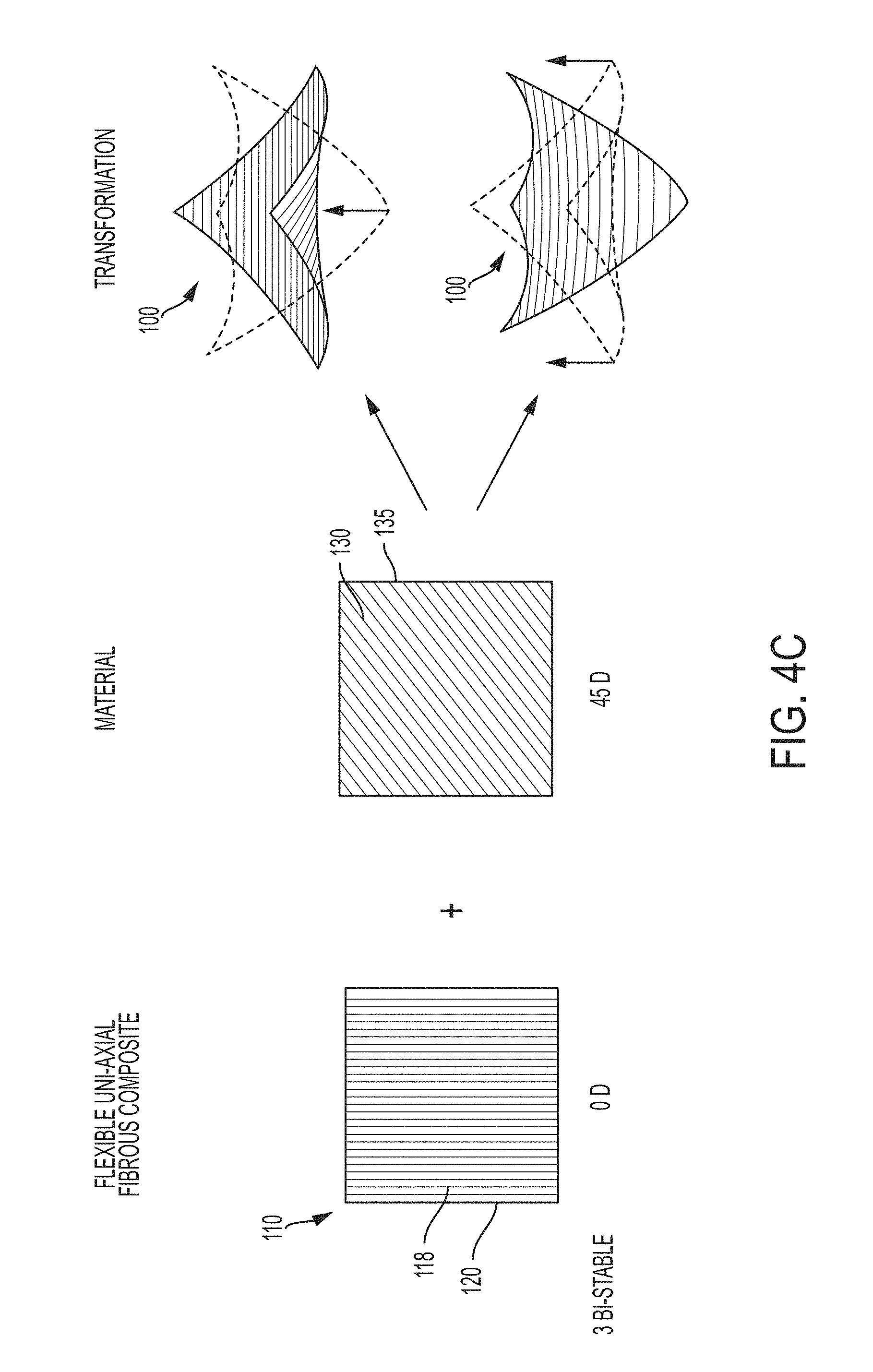
4. The self-transforming structure of claim 2, wherein the grain pattern of the added material is 45.degree. to an axis of a fiber of the flexible, carbon fiber composite.
5. The self-transforming structure of claim 2, wherein the grain of the added material is oriented at a 45.degree. angle to the boundary of the flexible, carbon fiber composite.
6. The self-transforming structure of claim 2, wherein the grain of the added material is orthogonal to the boundary of the flexible, carbon fiber composite.
7. The self-transforming structure of claim 2, wherein the length of the boundary of the added material is shorter than the length of the boundary of the flexible, carbon fiber composite.
8. The self-transforming structure of claim 2, wherein the length of the boundary of the added material is the same as the length of the boundary of the flexible, carbon fiber composite.
9. The self-transforming structure of claim 2, wherein the fibers of the flexible, carbon fiber composite are oriented at 45.degree. angles relative to the boundary of the flexible, carbon fiber composite.
10. The self-transforming structure of claim 2, wherein the fibers of the flexible, carbon fiber composite are orthogonal to the boundary of the flexible, carbon fiber composite.
11. The self-transforming structure of claim 2, wherein the flexible, carbon fiber composite is square, rectangular, or round.
12. The self-transforming structure of claim 2, wherein the flexible, carbon fiber composite is rectangular.
13. The self-transforming structure of claim 2, wherein: a) the grain of the added material is orthogonal to an axis of a fiber of the flexible, carbon fiber composite; b) the grain of the added material is oriented at 45.degree. relative to the boundary of the flexible, carbon fiber composite; c) the length of the boundary of the added material is shorter than the length of the boundary of the flexible, carbon fiber composite; and d) the fibers of the flexible, carbon fiber composite are oriented at 45.degree. relative to the boundary of the flexible, carbon fiber composite.
14. The self-transforming structure of claim 2, wherein: a) the grain of the added material is orthogonal to an axis of a fiber of the flexible, carbon fiber composite; b) the grain of the added material is oriented at 45.degree. relative to the boundary of the flexible, carbon fiber composite; c) the length of the boundary of the added material is the same as the length of the boundary of the flexible, carbon fiber composite; and d) the fibers of the flexible, carbon fiber composite are oriented at 45.degree. relative to the boundary of the flexible, carbon fiber composite.
15. The self-transforming structure of claim 2, wherein: a) the grain of the added material is orthogonal relative to an axis of a fiber of the flexible, carbon fiber composite; b) the grain of the added material is orthogonal relative to the boundary of the flexible, carbon fiber composite; c) the length of the boundary of the added material is shorter than the length of the boundary of the flexible, carbon fiber composite; and d) the fibers of the flexible, carbon fiber composite are orthogonal relative to the boundary of the flexible, carbon fiber composite.
16. The self-transforming structure of claim 2, wherein: a) the grain of the added material is oriented at a 45.degree. angle relative to an axis of a fiber of the flexible, carbon fiber composite; b) the grain of the added material is orthogonal relative to the boundary of the flexible, carbon fiber composite; c) the length of the boundary of the added material is the same length as the boundary of the flexible, carbon fiber composite; and d) the fibers of the flexible, carbon fiber composite are oriented at a 45.degree. angle relative to the boundary of the flexible, carbon fiber composite.
17. The self-transforming structure of claim 13, wherein substantially parallel grains of the added material are on opposite surfaces of the flexible, carbon fiber composite.
18. The self-transforming structure of claim 5, wherein: a) the grain of the added material is orthogonal to an axis of a fiber of the flexible, carbon fiber composite; b) the grain of the added material is oriented at 45.degree. relative to the boundary of the flexible, carbon fiber composite; c) the length of the boundary of the added material is the same as the length of the boundary of the flexible, carbon fiber composite; and d) the fibers of the flexible, carbon fiber composite are oriented at 45.degree. relative to the boundary of the flexible, carbon fiber composite, and wherein the added material provides equal forces in two directions, thereby providing bi-stability.
19. The self-transforming structure of claim 1, wherein the fibers of the flexible, carbon fiber composite are oriented triaxially.
20. The self-transforming structure of claim 19, wherein the grain of the added material is orthogonal to an axis of a fiber of the flexible, carbon fiber composite.
21. The self-transforming structure of claim 19, wherein the grain of the added material is oriented at an angle of 0.degree., 60.degree., or 120.degree. relative to the boundary of the flexible, carbon fiber composite.
22. The self-transforming structure of claim 19, wherein the length of the boundary of the added material is the same length as the boundary of the flexible, carbon fiber composite.
23. The self-transforming structure of claim 19, wherein the fibers of the flexible, carbon fiber composite are oriented at 60.degree. and 120.degree. angles relative to the boundary of the flexible, carbon fiber composite.
24. The self-transforming structure of claim 19, wherein: a) the grain of the added material is orthogonal to an axis of a fiber of the flexible, carbon fiber composite; b) the grain of the added material is oriented at a 0.degree. angle relative to the boundary of the flexible, carbon fiber composite; c) the length of the boundary of the added material is the same length as the boundary of the flexible, carbon fiber composite; and d) the fibers of the flexible, carbon fiber composite are oriented at 60.degree. and 120.degree. angles relative to the boundary of the flexible, carbon fiber composite.
25. The self-transforming structure of claim 19, wherein: a) the grain of the added material is orthogonal to an axis of a fiber of the flexible, carbon fiber composite; b) the grain of the added material is oriented at a 60.degree. angle relative to the boundary of the flexible, carbon fiber composite; c) the length of the boundary of the added material is the same length as the boundary of the flexible, carbon fiber composite; and d) the fibers of the flexible, carbon fiber composite are oriented at 60.degree. and 120.degree. angles relative to the boundary of the flexible, carbon fiber composite.
26. The self-transforming structure of claim 19, wherein: a) the grain of the added material is orthogonal to an axis of a fiber of the flexible, carbon fiber composite; b) the grain of the added material is oriented at a 120.degree. angle relative to the boundary of the flexible, carbon fiber composite; c) the length of the boundary of the added material is the same length as the boundary of the flexible, carbon fiber composite; and d) the fibers of the flexible, carbon fiber composite are oriented at 60.degree. and 120.degree. angles relative to the boundary of the flexible, carbon fiber composite.
27. The self-transforming structure of claim 1, wherein the fibers of the flexible, carbon fiber composite are uniaxial.
28. The self-transforming structure of claim 27, wherein the grain of the added material is orthogonal to an axis of a fiber of the flexible, carbon fiber composite.
29. The self-transforming structure of claim 27, wherein the grain of the added material is oriented at an angle of 0.degree., orthogonal, or 45.degree. relative to the boundary of the flexible, carbon fiber composite.
30. The self-transforming structure of claim 27, wherein the length of the boundary of the added material is the same length as the boundary of the flexible, carbon fiber composite.
31. The self-transforming structure of claim 27, wherein the fibers of the flexible, carbon fiber composite are orthogonal relative to the boundary of the flexible, carbon fiber composite.
32. The self-transforming structure of claim 27, wherein: a) the grain of the added material is orthogonal to an axis of a fiber of the flexible, carbon fiber composite; b) the grain of the added material is oriented at a 0.degree. angle relative to the boundary of the flexible, carbon fiber composite; c) the length of the boundary of the added material is the same length as the boundary of the flexible, carbon fiber composite; and d) the fibers of the flexible, carbon fiber composite are orthogonal to the boundary of the flexible, carbon fiber composite.
33. The self-transforming structure of claim 27, wherein: a) the grain of the added material is orthogonal to an axis of a fiber of the flexible, carbon fiber composite; b) the grain of the added material is orthogonal to the boundary of the flexible, carbon fiber composite; c) the length of the boundary of the added material is the same length as the boundary of the flexible, carbon fiber composite; and d) the fibers of the flexible, carbon fiber composite are orthogonal to the boundary of the flexible, carbon fiber composite.
34. The self-transforming structure of claim 27, wherein: a) the grain of the added material is orthogonal to an axis of a fiber of the flexible, carbon fiber composite; b) the grain of the added material is oriented at a 45.degree. angle relative to the boundary of the flexible, carbon fiber composite; c) the length of the boundary of the added material is the same length as the boundary of the flexible, carbon fiber composite; and d) the fibers of the flexible, carbon fiber composite are orthogonal to the boundary of the flexible, carbon fiber composite.
35. The self-transforming structure of claim 1, wherein the external stimulus can be exposure to a temperature change.
36. The self-transforming structure of claim 35, wherein the temperature change can be caused by a laser, infrared light, or electrical resistive heating.
37. The self-transforming structure of claim 1, wherein the external stimulus can be exposure to water or removal of exposure to water.
38. A method of making a self-transforming structure, the method comprising: coupling an added material to a surface of a flexible, carbon fiber composite to form a structure, the flexible, carbon fiber composite having a boundary and fibers along one or more axes, wherein the added material is selected from the group consisting of nylon, biaxially-oriented polyethylene terephthalate (BoPET) and polypropylene, wherein the added material has a boundary and a grain pattern, the grain pattern consisting of substantially parallel grains, wherein the flexible, carbon fiber composite and the added material have different coefficients of expansion in response to an external stimulus to cause the structure to self-transform, and wherein the grain pattern of the added material is oriented relative to the fibers of the flexible, carbon fiber composite to enable predictable self-transformation of the structure responsive to the external stimulus.
39. The method of claim 38, wherein coupling the added material to the flexible, carbon fiber composite comprises printing the added material onto the flexible, carbon fiber composite by additive manufacturing.
40. The method of claim 38, wherein coupling the added material to the flexible, carbon fiber composite comprises laminating the added material onto the flexible, carbon fiber composite.
Description
BACKGROUND OF THE INVENTION
Additive manufacturing, sometimes referred to as "3D printing," permits the precise application of materials onto substrates. Recent advances in 3D printing have enabled the fabrication of printed objects encoded with predicted shape change. These objects can transform over time from a first, printed shape to a second, predetermined shape.
SUMMARY OF THE INVENTION
Described herein is a self-transforming structure. The self-transforming structure includes a flexible, fibrous composite having a boundary and fibers along one or more axes that form a weave pattern, and an added material having a grain pattern. The added material can be coupled to the flexible, fibrous composite to form a structure. The flexible, fibrous composite and the added material have different expansion or contraction rates in response to an external stimulus to cause the structure to self-transform. The grain pattern of the added material can be oriented relative the weave pattern of the flexible, fibrous composite to cause a predictable self-transformation of the structure responsive to the external stimulus. The flexible, fibrous composite can be carbon fiber, glass fiber, basalt fiber, liquid crystal polymers, and hybrids thereof.
The weave pattern of the flexible, fibrous composite can be biaxial. The grain pattern of the added material can be orthogonal, oriented at a 45.degree. angle, or oriented at any other angle to an axis of a fiber of the flexible, fibrous composite. The grain pattern of the added material can be 45.degree. to an axis of a fiber of the flexible, fibrous composite. The grain of the added material can be oriented at a 45.degree. angle to a boundary of the flexible, fibrous composite. The grain of the added material can be orthogonal to a boundary of the flexible, fibrous composite. The length of the boundary of the added material can be shorter than the length of the boundary of the flexible, fibrous composite. The length of the boundary of the added material can be the same as the length of the boundary of the flexible, fibrous composite. The fibers of the flexible, fibrous added material can be oriented at 45.degree. angles relative to the boundary of the flexible, fibrous composite. The fibers of the flexible, fibrous added material can be orthogonal to the boundary of the flexible, fibrous composite. The flexible, fibrous composite can be square, rectangular, round, or an arbitrary shape. The flexible, fibrous composite can be rectangular.
In one embodiment having a biaxial, flexible fibrous composite, a) the grain of the added material can be orthogonal to an axis of a fiber of the flexible, fibrous composite; b) the grain of the added material can be oriented at 45.degree. relative to the boundary of the flexible, fibrous composite; c) the length of the boundary of the added material can be shorter than the length of the boundary of the flexible, fibrous composite; and d) the fibers of the flexible, fibrous composite can be oriented at 45.degree. relative to the boundary of the flexible, fibrous composite.
In another embodiment having a biaxial, flexible fibrous composite, a) the grain of the added material can be orthogonal to an axis of a fiber of the flexible, fibrous composite; b) the grain of the added material can be oriented at 45.degree. relative to the boundary of the flexible, fibrous composite; c) the length of the boundary of the added material can be the same as the length of the boundary of the flexible, fibrous composite; and d) the fibers of the flexible, fibrous composite are oriented at 45.degree. relative to the boundary of the flexible, fibrous composite.
In another embodiment having a biaxial, flexible fibrous composite, a) the grain of the added material can be orthogonal relative to an axis of a fiber of the flexible, fibrous composite; b) the grain of the added material can be orthogonal relative to the boundary of the flexible, fibrous composite; c) the length of the boundary of the added material can be shorter than the length of the boundary of the flexible, fibrous composite; and d) the fibers of the flexible, fibrous composite are orthogonal relative to the boundary of the flexible, fibrous composite.
In another embodiment having a biaxial, flexible fibrous composite, a) the grain of the added material can be oriented at a 45.degree. angle relative to an axis of a fiber of the flexible, fibrous composite; b) the grain of the added material can be orthogonal relative to the boundary of the flexible, fibrous composite; c) the length of the boundary of the added material can be the same length as the boundary of the flexible, fibrous composite; and d) the fibers of the flexible, fibrous composite are oriented at a 45.degree. angle relative to the boundary of the flexible, fibrous composite. In some instances, parallel grains of the added material can be on opposite sides of the flexible, fibrous composite.
In another embodiment having a biaxial, flexible fibrous composite, a) the grain of the added material can be orthogonal to an axis of a fiber of the flexible, fibrous composite; b) the grain of the added material can be oriented at 45.degree. relative to the boundary of the flexible, fibrous composite; c) the length of the boundary of the added material can be the same as the length of the boundary of the flexible, fibrous composite; and d) the fibers of the flexible, fibrous composite are oriented at 45.degree. relative to the boundary of the flexible, fibrous composite. Additionally, the added material can provide equal forces in two directions, thereby providing bi-stability.
The weave pattern of the flexible, fibrous composite can be triaxial. The grain of the added material can be orthogonal to an axis of a fiber of the flexible, fibrous composite. The grain of the added material can be oriented at an angle of 0.degree., 60.degree., or 120.degree. relative to the boundary of the flexible, fibrous composite. The length of the boundary of the added material can be the same length as the boundary of the flexible, fibrous composite. The fibers of the flexible, fibrous composite are oriented at 60.degree. and 120.degree. angles relative to the boundary of the flexible, fibrous composite.
In one embodiment having a triaxial, flexible fibrous composite, a) the grain of the added material can be orthogonal to an axis of a fiber of the flexible, fibrous composite; b) the grain of the added material can be oriented at a 0.degree. angle relative to the boundary of the flexible, fibrous composite; c) the length of the boundary of the added material can be the same length as the boundary of the flexible, fibrous composite; and d) the fibers of the flexible, fibrous composite are oriented at 60.degree. and 120.degree. angles relative to the boundary of the flexible, fibrous composite.
In one embodiment having a triaxial, flexible fibrous composite, a) the grain of the added material can be orthogonal to an axis of a fiber of the flexible, fibrous composite; b) the grain of the added material can be oriented at a 60.degree. angle relative to the boundary of the flexible, fibrous composite; c) the length of the boundary of the added material can be the same length as the boundary of the flexible, fibrous composite; and d) the fibers of the flexible, fibrous composite are oriented at 60.degree. and 120.degree. angles relative to the boundary of the flexible, fibrous composite.
In one embodiment having a triaxial, flexible fibrous composite, a) the grain of the added material can be orthogonal to an axis of a fiber of the flexible, fibrous composite; b) the grain of the added material can be oriented at a 120.degree. angle relative to the boundary of the flexible, fibrous composite; c) the length of the boundary of the added material can be the same length as the boundary of the flexible, fibrous composite; and d) the fibers of the flexible, fibrous composite are oriented at 60.degree. and 120.degree. angles relative to the boundary of the flexible, fibrous composite.
The weave pattern of the flexible, fibrous composite can be uniaxial. The grain of the added material can be orthogonal to an axis of a fiber of the flexible, fibrous composite. The grain of the added material can be oriented at an angle of 0.degree., orthogonal, or 45.degree. relative to the boundary of the flexible, fibrous composite. The length of the boundary of the added material can be the same length as the boundary of the flexible, fibrous composite. The fibers of the flexible, fibrous composite can be orthogonal relative to the boundary of the flexible, fibrous composite.
In one embodiment having a uniaxial, flexible fibrous composite, a) the grain of the added material can be orthogonal to an axis of a fiber of the flexible, fibrous composite; b) the grain of the added material can be oriented at a 0.degree. angle relative to the boundary of the flexible, fibrous composite; c) the length of the boundary of the added material can be the same length as the boundary of the flexible, fibrous composite; and d) the fibers of the flexible, fibrous composite can be orthogonal to the boundary of the flexible, fibrous composite.
In one embodiment having a uniaxial, flexible fibrous composite, a) the grain of the added material can be orthogonal to an axis of a fiber of the flexible, fibrous composite; b) the grain of the added material can be orthogonal to the boundary of the flexible, fibrous composite; c) the length of the boundary of the added material can be the same length as the boundary of the flexible, fibrous composite; and d) the fibers of the flexible, fibrous composite can be orthogonal to the boundary of the flexible, fibrous composite.
In one embodiment having a uniaxial, flexible fibrous composite, a) the grain of the added material can be orthogonal to an axis of a fiber of the flexible, fibrous composite; b) the grain of the added material can be oriented at a 45.degree. angle relative to the boundary of the flexible, fibrous composite; c) the length of the boundary of the added material can be the same length as the boundary of the flexible, fibrous composite; and d) the fibers of the flexible, fibrous composite can be orthogonal to the boundary of the flexible, fibrous composite.
The external stimulus can be exposure to a temperature change. In some instances, exposure to a temperature change can be caused by a laser, infrared light, or electrical resistive heating. The external stimulus can be exposure to water or removal of exposure to water.
Described herein is a method of making a self-transforming structure. The method can include coupling an added material to a flexible, fibrous composite to form a structure. The flexible, fibrous composite can have a boundary and fibers along axes that form a weave pattern. The flexible, fibrous composite and the added material can have different expansion or contraction rates in response to an external stimulus to cause the structure to self-transform. The added material can have a grain pattern oriented relative the weave pattern of the flexible, fibrous composite. Coupling the added material to the flexible, fibrous composite can include printing the added material onto the flexible, fibrous composite by additive manufacturing. Coupling the added material to the flexible, fibrous composite can include laminating the added material onto the flexible, fibrous composite.
The methods and resulting products described herein provide numerous advantages compared to prior 3D printed structures. Flexible, fibrous composite composites have an ordered structure that provides strength and elasticity, which provide benefits in self-transforming structures. The self-transforming structure can be packaged in a flat configuration, and later transformed into a three-dimensional structure at a later time or at a different location.
The self-transforming structures described herein have applications in numerous industries, including aviation, automotive, apparel/footwear, furniture, and building materials.
BRIEF DESCRIPTION OF THE DRAWINGS
The foregoing will be apparent from the following more particular description of example embodiments of the invention, as illustrated in the accompanying drawings in which like reference characters refer to the same parts throughout the different views. The drawings are not necessarily to scale, emphasis instead being placed upon illustrating embodiments of the present invention.
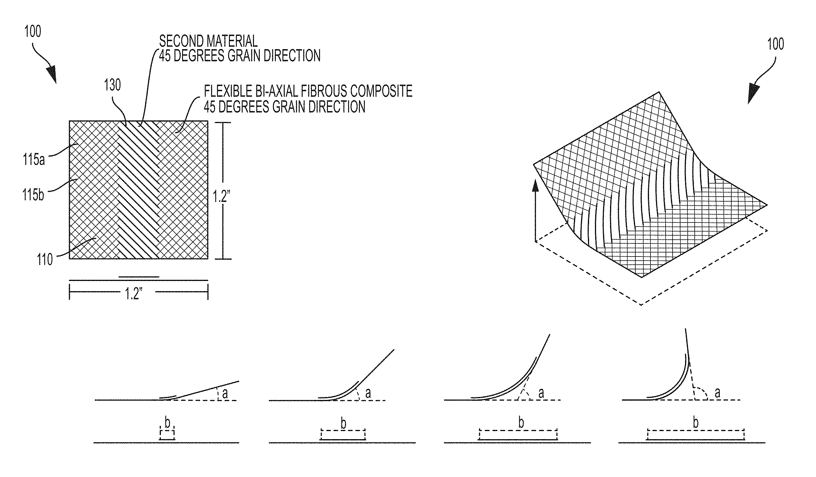
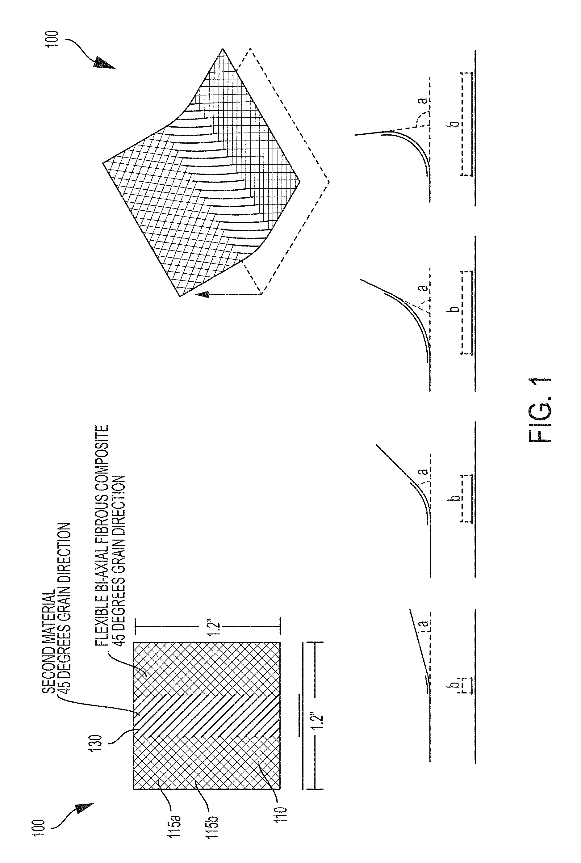
FIG. 1 is an illustration of an embodiment showing self-transformation angles. The angle of self-transformation (a) varies depending on the width (b) of the added material.
FIGS. 2A-G are illustrations of transformations on a biaxial fibrous composite: 2A) Fold; 2B) Curve; 2C) Twist; 2D) Spiral; 2E) Wave; 2F) Bi-stable transformation; G) Fold.
FIGS. 3A-C are illustrations of transformation on a triaxial fibrous composite: 3A) Curve; 3B) Curve; 3C) Curve.
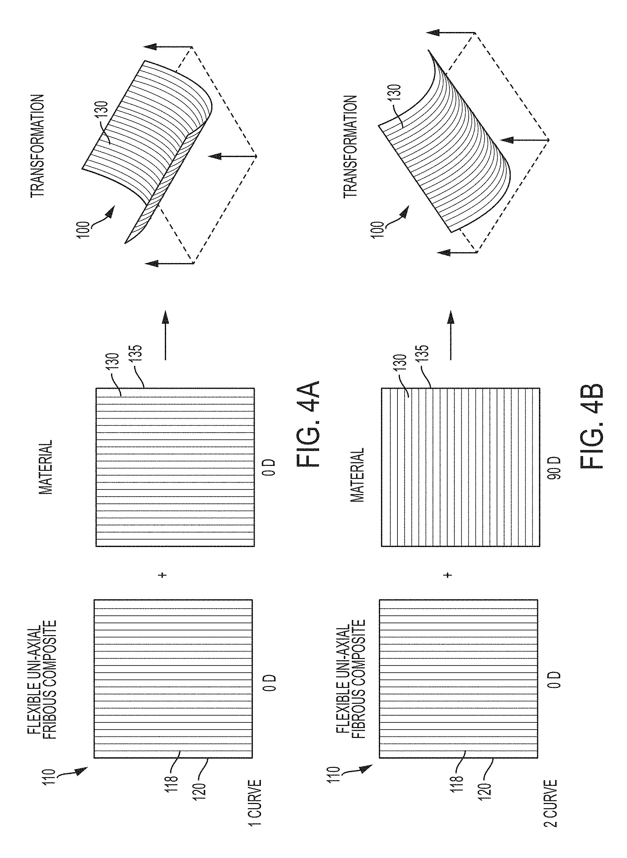
FIGS. 4A-C are illustrations of transformations on a uniaxial fibrous composite: 4A) Curve; 4B) Curve; 4C) Bi-stable transformation.
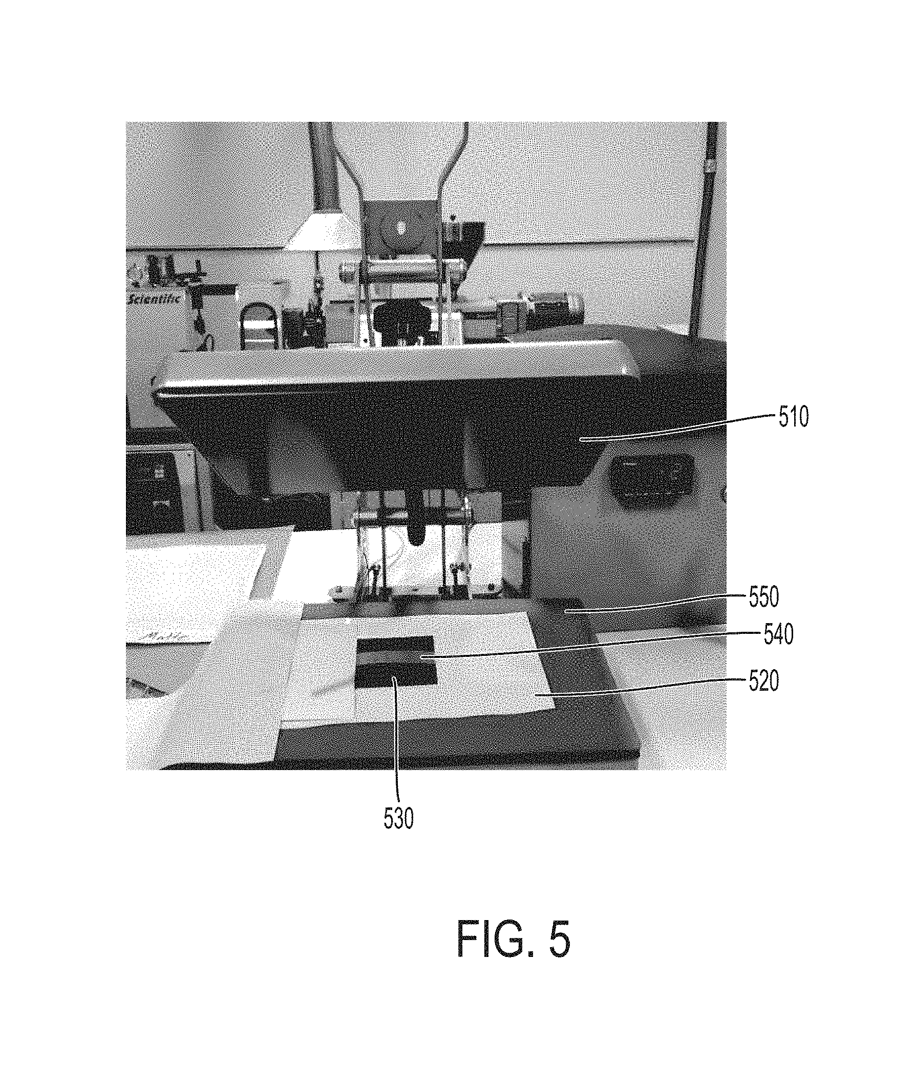
FIG. 5 is an annotated photograph of an experimental setup for making a self-transforming structure.
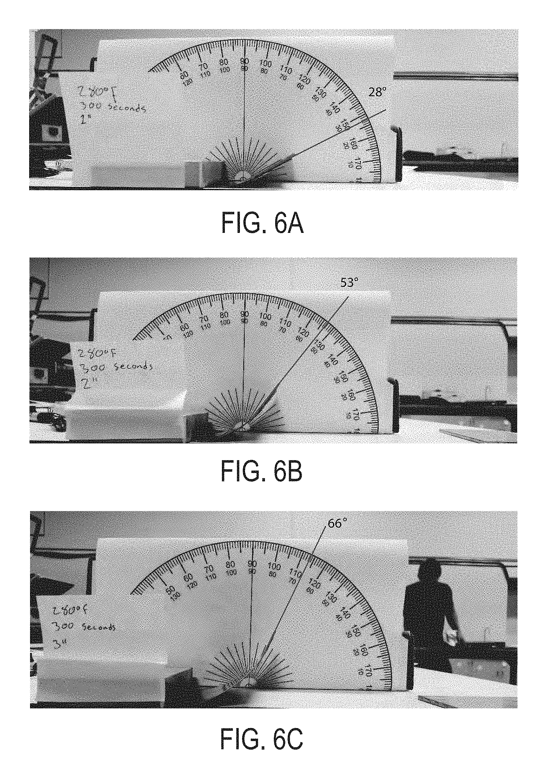
FIGS. 6A-C are photographs of observed transformation for one inch, two inch, and three inch nylon strips laminated onto a four inch-by-four inch flexible carbon fiber sample at 280.degree. F. for 300 seconds.
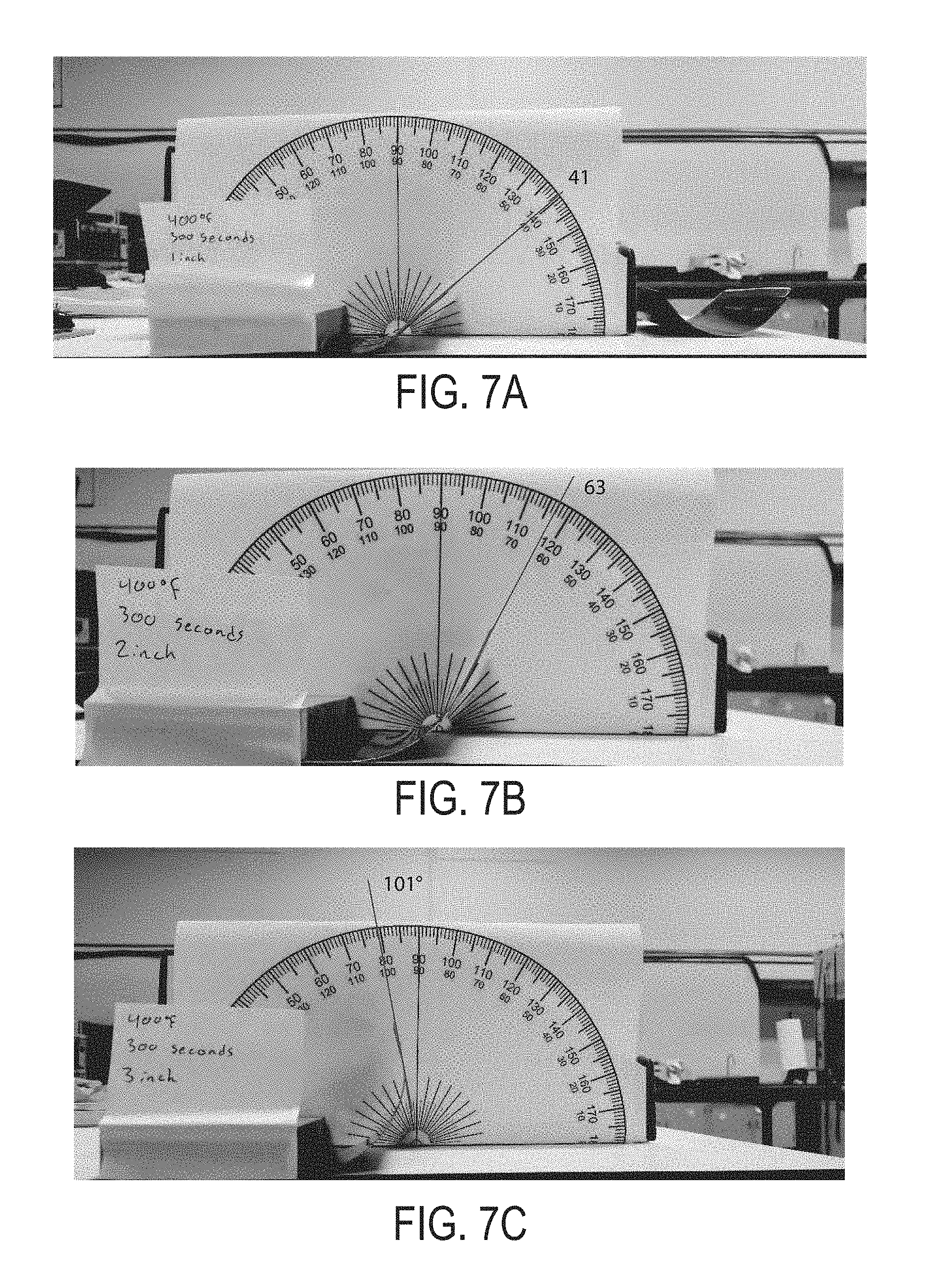
FIGS. 7A-C are photographs of observed transformation for one inch, two inch, and three inch nylon strips laminated onto a four inch-by-four inch flexible carbon fiber sample at 400.degree. F. for 300 seconds.
FIGS. 8A and 8B are illustrations showing nylon coupled to a carbon fiber. FIG. 8A shows nylon adjacent to carbon fiber prior to lamination. FIG. 8B shows nylon coupled to carbon fiber after lamination and the shape transformation that has occurred.
FIG. 9 is an annotated photograph of an experimental setup for observing temperature-dependent self-transformation.
FIGS. 10A-I are a series of photographs showing the transformation over time (mm:ss). A) Time=0:00, Temperature=83.degree. F.; B) Time=1:00, Temperature=119.degree. F.; C) Time=2:00, Temperature=150.degree. F.; D) Time=3:00, Temperature=187.degree. F.; E) Time=4:00, Temperature=221.degree. F.; F) Time=5:00, Temperature=240.degree. F.; G) Time=7:00, Temperature=246.degree. F.; H) Time=10:12, Temperature=261.degree. F.; I) Time=10:32, Temperature=273.degree. F.
FIG. 11 is a graph showing the change in the angle of self-transformation as temperature increases.
FIG. 12A is a series of time-lapsed photographs showing a twisting transformation. FIG. 12B shows superimposed photos of a time-lapsed twisting transformation.
FIG. 13A is a series of time-lapsed photographs showing a folding transformation. FIG. 13B shows superimposed photos of a time-lapsed folding transformation.
FIG. 14 is a time-lapse photograph showing the self-transformation of programmable carbon fiber within a jet engine air inlet. The dynamic carbon fiber regulates the amount of airflow for active engine cooling.
FIG. 15 is an example of a triaxial weave with 22 mm wide strips of fiber woven in 0 degree, +60 degree and -60 degree orientation. The laminated sheet on top of the weave can be placed in-line with the fiber orientation at 0.degree., 120.degree., or 60.degree. to achieve a 1-curve, 2-curve, or 3-curve type behavior, respectively.
FIG. 16 is an example of a uniaxial weave orientation. The print pattern on top of the weave can be placed in-line with the fiber orientation or at 90.degree. to achieve a 1-fold or 2-fold type behavior, respectively.
FIGS. 17A and 17B are photographs of self-transforming structures made using a triaxial flexible, fibrous composite. The grain direction of the added material is indicated with arrows and is patterned as illustrated in FIG. 3A.
FIGS. 18A-D are photographs of self-transforming structures made using a biaxial flexible, fibrous composite. A) Curve; B) Fold; C) Wave; D) Spiral.
DETAILED DESCRIPTION OF THE INVENTION
A description of example embodiments of the invention follows.
Self-transforming structures according to example embodiments can be made according to the processes described herein. In general, a flexible, fibrous composite provides a substrate for an added material. Together, the flexible, fibrous composite and the added material form a combined structure. The flexible, fibrous composite and the added material typically have different expansion or contraction rates in response to an external stimulus, which causes the combined structure to self-transform upon exposure to the external stimulus.
As used herein, the term "weave pattern" refers to an ordered arrangement of fibers, which can be intersecting or non-intersecting. Examples of intersecting weave patterns include biaxial and triaxial weave patterns. An example of a nonintersecting weave pattern is a uniaxial weave pattern.
As used herein, a "flexible, fibrous composite" is a composite that provides sufficient ability to bend without delaminating or detaching from the added material coupled to it. Thus, when the self-transforming structure is exposed to an external stimulus, thereby causing the flexible, fibrous composite and the added material to have different expansion or contraction rates, the added material remains laminated or coupled to the flexible, fibrous composite, thereby causing a transformation in shape. Methods of making a flexible, fibrous composite are described in U.S. Patent Publication No. 2015/0174885.
Typically, a flexible, fibrous composite has at least one boundary, and often times more than one boundary. For example, a circular flexible, fibrous composite, as well as flexible fibrous composites having complex curved shapes, have a single boundary. A triangular flexible, fibrous composite has three boundaries. While many of the embodiments described herein are square or rectangular, the principles described are equally applicable to flexible, fibrous composites having other geometric shapes, as well as to flexible, fibrous composites having complex shapes. In these instances, descriptions of orientations relative to a boundary refer to the orientation at any position along a boundary.
Biaxial Weave Patterns and Oriented, Added Material
Typically, the flexible, fibrous composite is formed of woven fibers. A variety of weave patterns are known in the art. The weave patterns described herein are generally referred to as uniaxial, biaxial, and triaxial. The added material is typically applied to the flexible, fibrous composite so that grains of the added material are patterned relative to the weave pattern.
FIG. 1 is an illustration of one embodiment of a self-transforming structure 100. The flexible, fibrous composite 110 forms a substrate for grains 130 of the added material. The flexible fibrous composite is formed of intersecting fibers 115a and 115b. In this particular embodiment, the fibers intersect at 90.degree. angles, though other angles of intersection are possible. In the particular example, the grains 130 of the added material are substantially parallel with the fibers 115a of the flexible, fibrous composite 110. In this embodiment, parallel grains of the added material are aligned with and at least partially overlay fibers 115a of the flexible, fibrous composite.
Unique orientations of the grain of the added material relative to the axis of the flexible, fibrous substrate can yield different transformations upon exposure to an external stimulus. Conceptually, four features define the relationship between a biaxial flexible, fibrous composite and the added material. First is the relationship of the grain pattern of the added material to an axis of a fiber of the flexible, fibrous composite. The grain pattern of the added material can be orthogonal to an axis of a fiber of the flexible fibrous composite, or it can be patterned at an angle, such as a 45.degree. angle, relative to an axis of the flexible fibrous composite. Second is the orientation of the grain of the added material relative to a boundary of the flexible, fibrous composite. The grain of the added material can be orthogonal at a boundary, or it can be patterned at an angle, such as a 45.degree. angle, relative to a boundary of the flexible, fibrous composite. Third is the length of a boundary of the added material in relation to the length of a boundary of the flexible, fibrous composite. The length of a boundary of the added material can be the same length as the length of a boundary of the flexible, fibrous composite. Alternatively, the length of a boundary of the added material can be shorter than a boundary of the flexible, fibrous composite. Fourth is the orientation of the fibers of the flexible, fibrous composite relative to a boundary of the flexible, fibrous composite. The fibers of the flexible, fibrous composite can be orthogonal to a boundary of the flexible, fibrous composite. Alternatively, the fibers of the flexible, fibrous composite can be angled, such as at a 45.degree. angle, relative to a boundary of the flexible, fibrous composite. As another optional fifth condition, the added material can be printed on opposing sides of the flexible, fibrous composite, one particular example of which is illustrated in FIG. 2E.
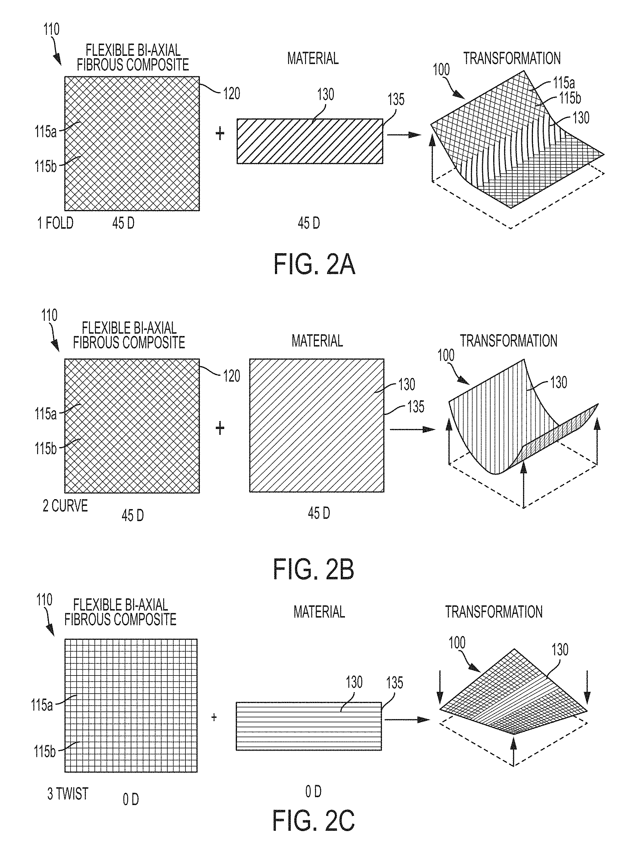
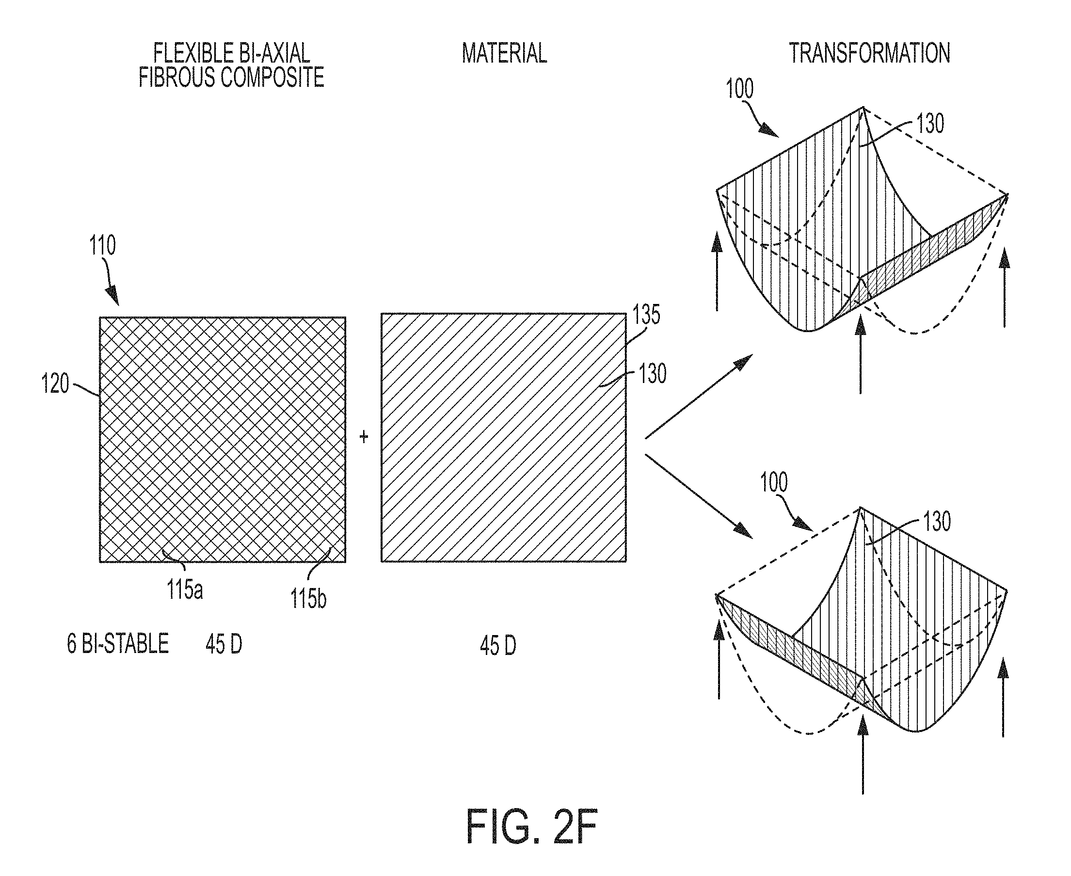
FIGS. 2A-F show six different types of transformations that can be created. In general, FIGS. 2A-F show the relative orientation of a biaxial flexible, fibrous composite and the added material that is coupled to it. The relationship between the four features described in the preceding paragraph and the embodiments of FIGS. 2A-F are summarized in Table 1. The notation underneath the images in the figures indicates the orientation of the fibers of the flexible fibrous composite (left) and the grains of the added material (middle) in degrees (e.g., in FIG. 2A, the orientation of the fibers is at a 45 degree angle relative to the horizon, and the orientation of the grains is also at a 45 degree angle relative to the horizon).
TABLE-US-00001 TABLE 1 Features of biaxial flexible, fibrous composite and added material illustrated in FIGS. 2A-F. 3. Length of a 1. Relationship of 2. Orientation of boundary of the 4. Orientation of the grain pattern the grain of the added material the fibers of the of added material added material in relation to flexible, fibrous to an axis of a relative to a the length of a composite relative fiber of the boundary of the boundary of the to a boundary of the FIG. and flexible, fibrous flexible, fibrous flexible, fibrous flexible, fibrous Transformation composite composite composite composite 2A: Fold Orthogonal 45.degree. to one another Shorter 45.degree. to one another 2B: Curve Orthogonal 45.degree. to one another Same length 45.degree. to one another 2C: Twist Orthogonal Orthogonal Shorter Orthogonal 2D: Spiral 45.degree. to one another Orthogonal Same length 45.degree. to one another 2E: Wave Orthogonal 45.degree. to one another Shorter 45.degree. to one another 2F: Bi-stable Orthogonal 45.degree. to one another Same length 45.degree. to one another 2G: Fold Orthogonal 45.degree. to two Shorter 45.degree. to one another boundaries
FIG. 2A shows a fold transformation. Parallel grains 130 of the added material are orthogonal to an axis of a fiber 115a of the flexible, fibrous composite, and coaxial with an axis of the other fiber 115b. The grain 130 of the added material is oriented at a 45.degree. angle relative to its own boundary 135 and relative to the boundary 120 of the flexible, fibrous composite. The length of a boundary 135 of the added material 130 is shorter than the length of a boundary 120 of the flexible, fibrous composite. The fibers 115a and 115b of the flexible, fibrous composite are oriented at a 45.degree. angle relative to its own boundary 120. In this particular example, the flexible, fibrous composite 110 is square; however, it need not be square in order to achieve a folding transformation.
FIG. 2B shows a curve transformation. Parallel grains 130 of the added material are orthogonal to an axis of a fiber 115a of the flexible, fibrous composite, and coaxial with an axis of the other fiber 115b. The grain 130 of the added material is oriented at a 45.degree. angle relative to its own boundary 135 and relative to the boundary 120 of the flexible, fibrous composite. The length of a boundary 135 of the added material 130 is the same, or substantially the same, as the length of a boundary 120 of the flexible, fibrous composite. The fibers 115a and 115b of the flexible, fibrous composite are oriented at a 45.degree. angle relative to its own boundary 120. In this particular example, the flexible, fibrous composite 110 is square; however, it need not be square in order to achieve a folding transformation. Unlike the fold shown in FIG. 2A, a curve can occur when the added material covers all, or substantially all, of a surface of the flexible, fibrous composite.
FIG. 2C shows a twist transformation. Parallel grains 130 of the added material are orthogonal to an axis of a fiber 115a of the flexible, fibrous composite, and coaxial with an axis of the other fiber 115b. The grain 130 of the added material is oriented orthogonally relative to its own boundary 135 and relative to the boundary 120 of the flexible, fibrous composite. The length of a boundary 135 of the added material 130 is shorter than the length of a boundary 120 of the flexible, fibrous composite. The fibers 115a and 115b of the flexible, fibrous composite are oriented orthogonally relative to its own boundary 120. The flexible, fibrous composite 110 is square; however, it need not be square in order to achieve a twist transformation.
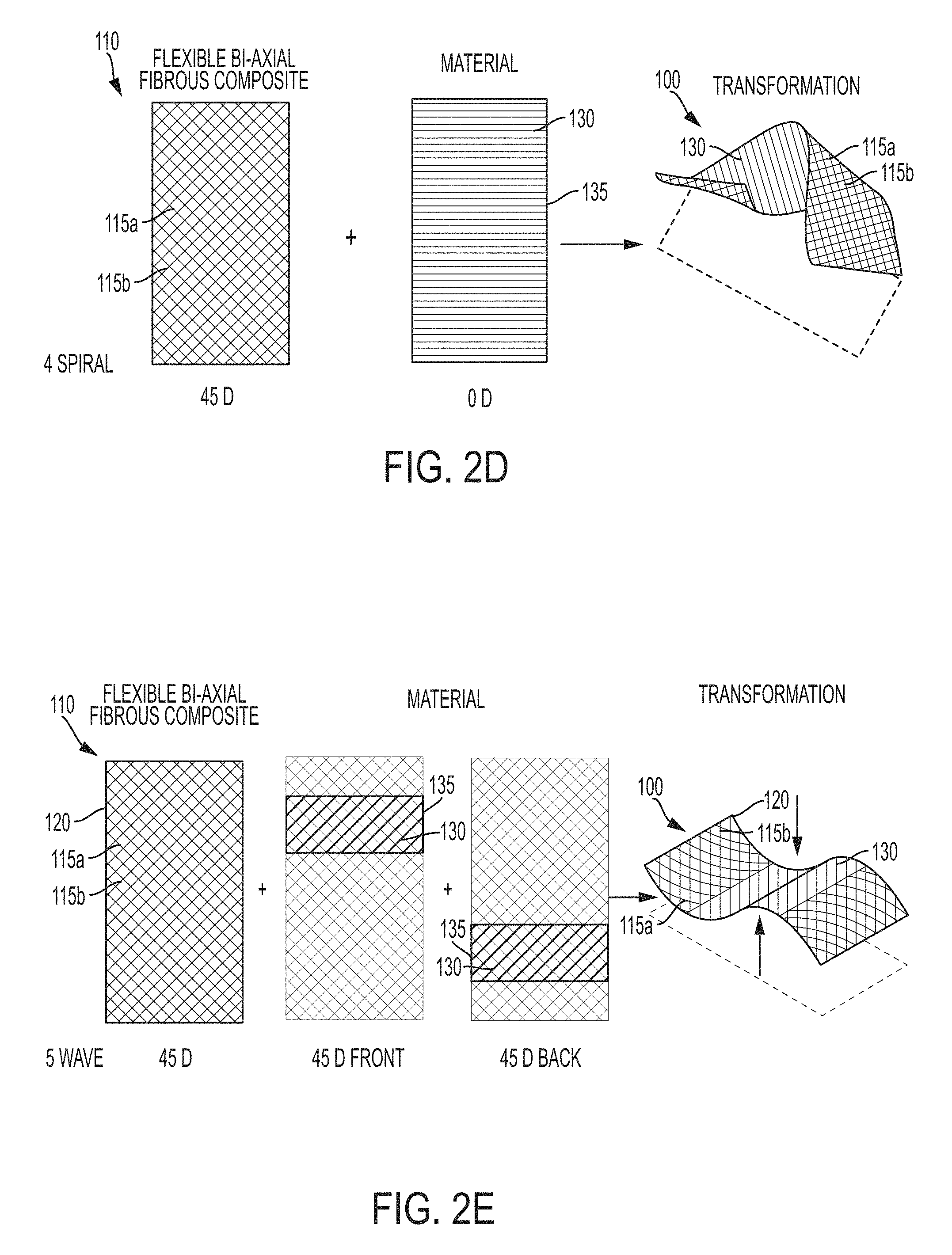
FIG. 2D shows a spiral transformation. Parallel grains 130 of the added material are oriented at 45.degree. angles relative to both axes of fiber 115a and 115b of the flexible, fibrous composite. The grain 130 of the added material is oriented orthogonally relative to its own boundary 135 and relative to the boundary 120 of the flexible, fibrous composite. The length of a boundary 135 of the added material 130 is the same as, or substantially similar to, the length of a boundary 120 of the flexible, fibrous composite. The fibers 115a and 115b of the flexible, fibrous composite are oriented at 45.degree. angles relative to its own boundary 120. Unlike the twist shown in FIG. 2C, a spiral can occur when the added material covers all, or substantially all, of a surface of the flexible, fibrous composite.
FIG. 2E shows a wave transformation. Parallel grains 130 of the added material are orthogonal to an axis of a fiber 115a of the flexible, fibrous composite, and coaxial with an axis of the other fiber 115b. The grain 130 of the added material is oriented at a 45.degree. angle relative to its own boundary 135 and relative to the boundary 120 of the flexible, fibrous composite. The length of a boundary 135 of the added material 130 is shorter than the length of a boundary 120 of the flexible, fibrous composite. The fibers 115a and 115b of the flexible, fibrous composite are oriented at a 45.degree. angle relative to its own boundary 120. The flexible, fibrous composite 110 is square; however, it need not be square in order to achieve a folding transformation. Conceptually, FIG. 2E builds upon FIG. 2A because it can be used to create two transformations like FIG. 2A, but on opposite sides of a flexible, fibrous composite. Although not illustrated, the added material can be oriented in different patterns on the first and sides of the flexible, fibrous composite, thereby creating even more unique structures.
FIG. 2F shows a bi-stable configuration. Parallel grains 130 of the added material are orthogonal to an axis of a fiber 115a of the flexible, fibrous composite, and coaxial with an axis of the other fiber 115b. The grain 130 of the added material is oriented at a 45.degree. angle relative to its own boundary 135 and relative to the boundary 120 of the flexible, fibrous composite. The length of a boundary 135 of the added material 130 is the same, or substantially the same, as the length of a boundary 120 of the flexible, fibrous composite. The fibers 115a and 115b of the flexible, fibrous composite are oriented at a 45.degree. angle relative to its own boundary 120. In this particular example, the flexible, fibrous composite 110 is square; however, it need not be square in order to achieve a folding transformation. The grains 130 are applied so that they create equal forces in both directions, leading to a configuration that is bi-stable. The flexible, fibrous composite 110 is square; however, it need not be square in order to achieve a folding transformation. The bi-stable configuration is thus a subset of the curve configuration illustrated in FIG. 2B. For example, a curve can be created that curls from tip to tip, rather than edge to edge like in 2B. The configuration can be bi-stable if the flexible, fibrous composite is square, which results in equal forces in opposite directions.
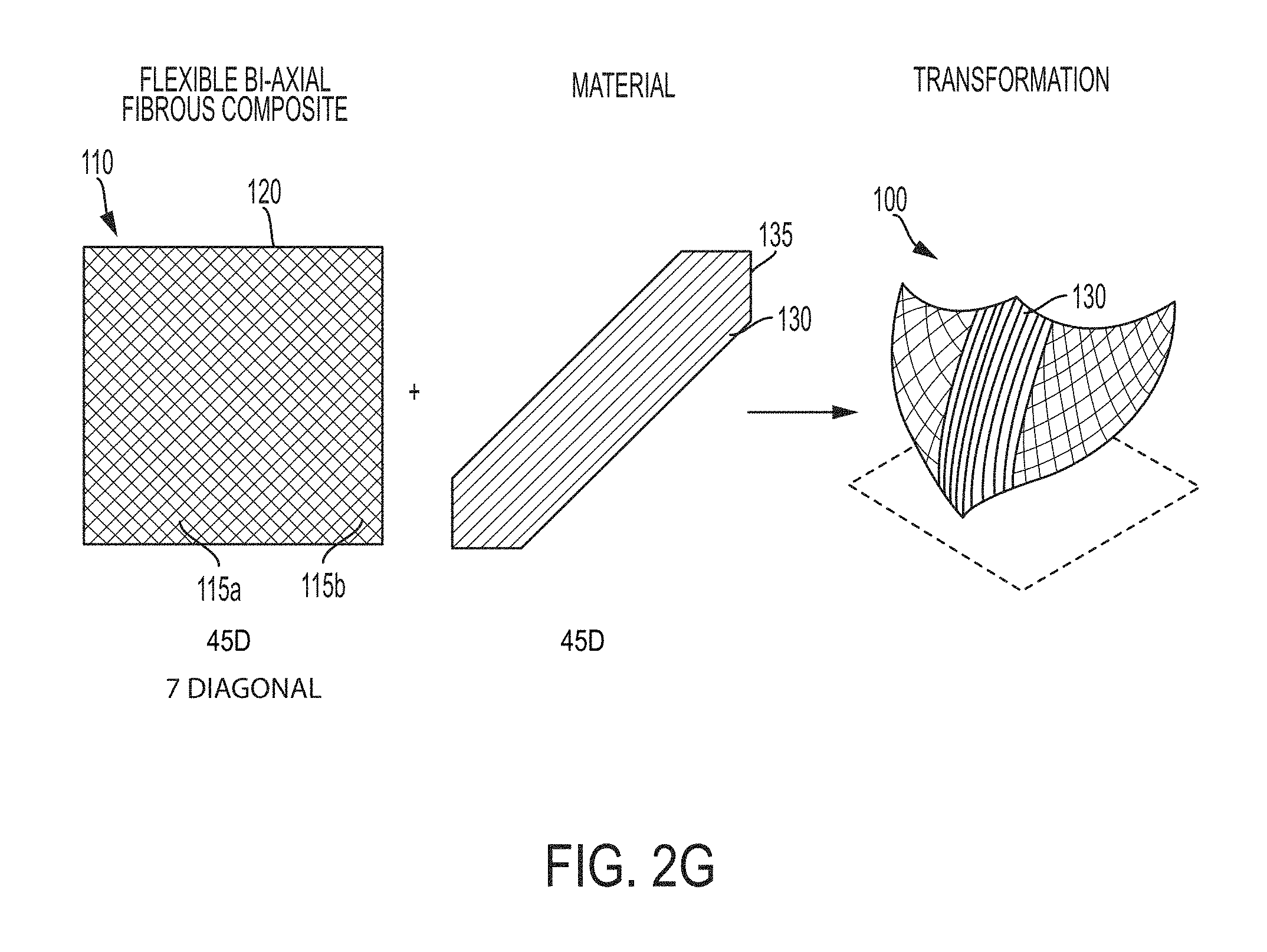
FIG. 2G shows a curve transformation. Parallel grains 130 of the added material are orthogonal to an axis of the fiber 115a of the flexible, flexible, fibrous composite, and coaxial with an axis of the other fiber 115b. The grain 130 of the added material is oriented at a 45.degree. angle relative to its own boundary 135 and relative to the boundary 120 of the flexible, fibrous composite. The length of a boundary 135 of the added material 130 is shorter than the length of two different boundaries 120 of the flexible, fibrous composite. The fibers 115a and 115b of the flexible, fibrous composite are oriented at a 45.degree. angle relative to its own boundary 120. In this particular example, the added material is applied across a diagonal of the flexible, fibrous composite 110, yielding the illustrated transformation.
Triaxial Weave Patterns and Oriented, Added Material
Unique orientations of the grain of the added material relative to the axis of the flexible, fibrous substrate can yield different transformation upon exposure to an external stimulus. Conceptually, two features define the relationship between a biaxial flexible, fibrous composite and the added material. First is the relationship of the grain pattern of the added material to an axis of a fiber of the flexible, fibrous composite. The triaxial weave pattern has fibers along three axes. Typically, the grain pattern of the added material will be coaxial with one of the axes, though it can be at an angle as well. Second is the orientation of the grain of the added material relative to a boundary of the flexible, fibrous composite. When the grain pattern of the added material is coaxial with one of the axes, the orientation can be 0.degree., 60.degree., or 120.degree. relative to a boundary of the flexible, fibrous composite. Third is the length of a boundary of the added material in relation to the length of a boundary of the flexible, fibrous composite. The length of a boundary of the added material can be the same length as the length of a boundary of the flexible, fibrous composite. Alternatively, the length of a boundary of the added material can be shorter than a boundary condition of the flexible, fibrous composite. Fourth is the orientation of the fibers of the flexible, fibrous composite relative to a boundary of the flexible, fibrous composite. Typically, the fibers of the flexible, fibrous composite are angled at 60.degree. and 120.degree. relative to a boundary of the flexible, fibrous composite, though other angles are possible as well. As another optional fifth condition, the added material can be printed on opposing sides of the flexible, fibrous composite.
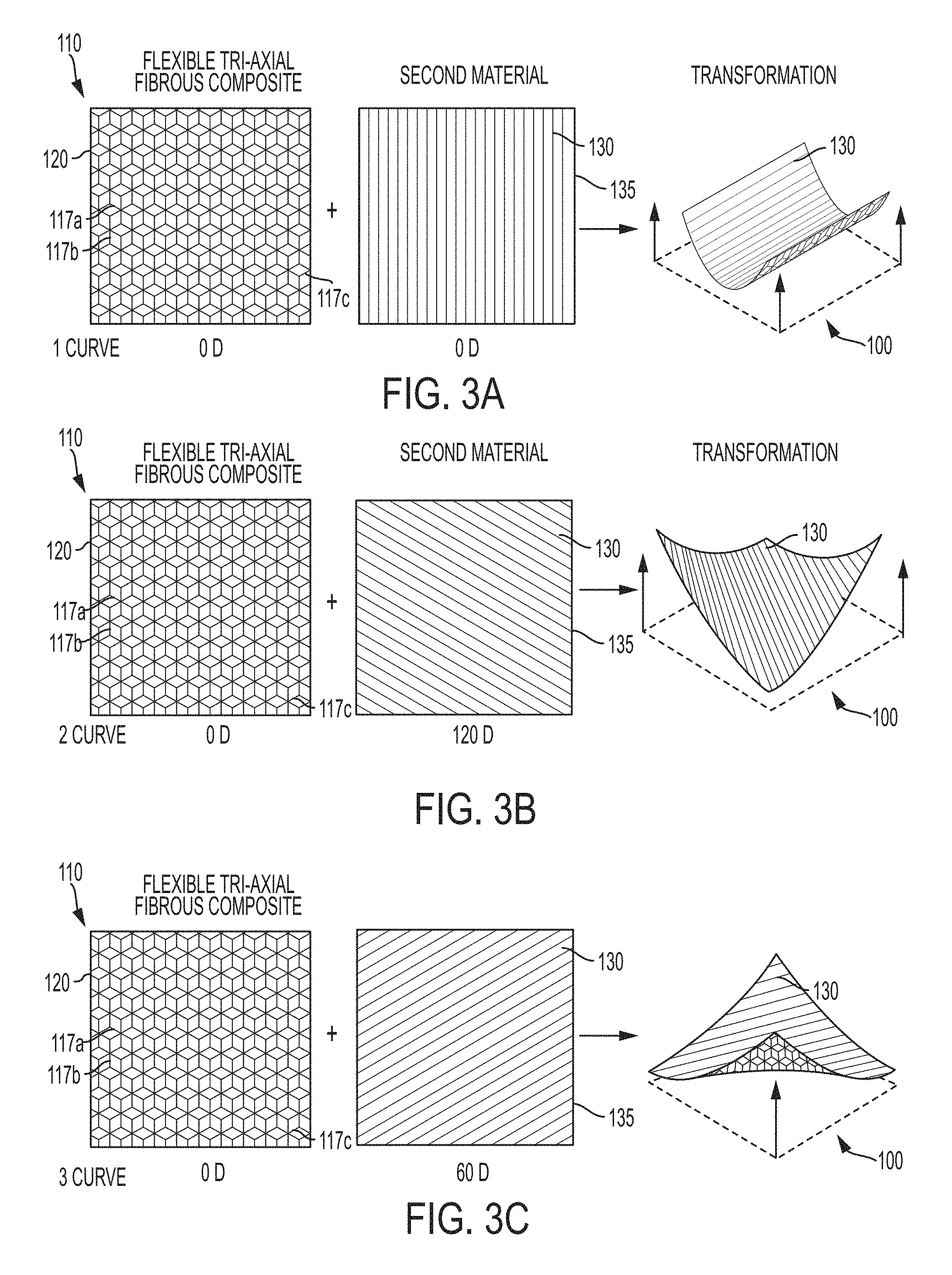
FIGS. 3A-C show three different types transformations that can be created. In general, FIGS. 3A-C show the relative orientation of a flexible, fibrous composite and the added material that is coupled to it. The relationship between the two features described in the preceding paragraph and the embodiments of FIGS. 3A-C are summarized in Table 2.
TABLE-US-00002 TABLE 2 Features of biaxial flexible, fibrous composite and added material illustrated in FIGS. 3A-C. 3. Length of a 1. Relationship of 2. Orientation of boundary of the 4. Orientation of the grain pattern the grain of the added material the fibers of the of added material added material in relation to flexible, fibrous to an axis of a relative to a the length of a composite relative fiber of the boundary of the boundary of the to a boundary of the FIG. and flexible, fibrous flexible, fibrous flexible, fibrous flexible, fibrous Transformation composite composite composite composite 3A: Curve Orthogonal 0.degree. to a boundary Same length 60.degree. and 120.degree. 3B: Curve Orthogonal 60.degree. to a boundary Same length 60.degree. and 120.degree. 3C: Curve Orthogonal 120.degree. to a boundary Same length 60.degree. and 120.degree.
FIGS. 3A-C show flexible fibrous composites having a triaxial weave pattern. In each of FIGS. 3A-C, the added material 130 is applied along an axis 117a,b,c of one of the fibers of the flexible, fibrous composite 110. Thus, each of the transformations in FIGS. 3A-C yields a similar transformation, though along a different axis.
Uniaxial Weave Patterns and Oriented, Added Material
Unique orientations of the grain of the added material relative to the axis of the flexible, fibrous substrate can yield different transformation upon exposure to an external stimulus. Conceptually, two features define the relationship between a biaxial flexible, fibrous composite and the added material. First is the orientation of the fibers of the flexible, fibrous composite to a boundary of the flexible, fibrous composite. Since the uniaxial weave pattern has fibers along one axis, typically the fibers are oriented orthogonally to a boundary of the flexible, fibrous composite. Second is the orientation of the grain of the added material relative to a boundary of the flexible, fibrous composite. The grain can be orthogonal to a boundary of the added material, parallel to a boundary of the added material, or oriented at an angle, such as a 45.degree. angle, relative to a boundary of the added material. Third is the length of a boundary of the added material in relation to the length of a boundary of the flexible, fibrous composite. The length of a boundary of the added material can be the same length as the length of a boundary of the flexible, fibrous composite. Alternatively, the length of a boundary of the added material can be shorter than a boundary condition of the flexible, fibrous composite. Fourth is the orientation of the fibers of the flexible, fibrous composite relative to a boundary of the flexible, fibrous composite. Typically, the fibers of the flexible, fibrous composite are orthogonal to one boundary (and thus parallel to another) of the flexible, fibrous composite, though other angles are possible as well. As another optional fifth condition, the added material can be printed on opposing sides of the flexible, fibrous composite.
FIGS. 4A-C show three different types transformations that can be created. In general, FIGS. 4A-C show the relative orientation of a flexible, fibrous composite and the added material that is coupled to it. In each of FIGS. 4A-C, the added material 138 is applied along an axis 118 of the fibers of the flexible, fibrous composite 110. The relationship between the two features described in the preceding paragraph and the embodiments of FIGS. 4A-C are summarized in Table 3.
TABLE-US-00003 TABLE 3 Features of biaxial flexible, fibrous composite and added material illustrated in FIGS. 3A-C. 1. Orientation of 3. Length of a the fibers of the 2. Orientation of boundary of the 4. Orientation of flexible, fibrous the grain of the added material the fibers of the composite added material in relation to flexible, fibrous relative to a relative to a the length of a composite relative boundary of the boundary of a boundary of the to a boundary of the FIG. and flexible, fibrous flexible, fibrous flexible, fibrous flexible, fibrous Transformation composite composite composite composite 4A: Curve Orthogonal 0.degree. to a boundary Same length Orthogonal 4B: Curve Orthogonal Orthogonal to a Same length Orthogonal boundary 4C: Bi-stable Orthogonal 45.degree. to a boundary Same length Orthogonal
FIGS. 4A-C show flexible, fibrous composites having a uniaxial weave pattern. In each of FIGS. 4A-C, the added material 130 is applied to the flexible, fibrous composite. The flexible, uniaxial fibrous composite has fibers 118 oriented in parallel strips.
Flexible, Fibrous Composites
A variety of composites are suitable for use as a flexible, fibrous composite. One example is carbon fiber. Other examples include glass fiber, basalt fiber, liquid crystal polymers/fibers, and hybrids thereof. In general, the flexible, fibrous composites described herein have different performance characteristics. For example, some are more flexible than others, and some have more tensile strength than others. Generally, the weave patterns of the flexible, fibrous composite remain similar. The amount and rate of transformation can vary depending on the type of materials and the number of fibers. Thus, thickness and width can be adjusted to achieve the proper contractive force to cause a shape change in view of the coefficient of thermal expansion of the flexible, fibrous composite and the added material. The greater the difference in the coefficient of thermal expansion, the greater the transformation effect. Polymer melt shrinkage and changes in the coefficient of thermal expansion can also influence magnitude of the transformation. For example, if the flexible, fibrous composite is a nylon fiber composite, and the added material is nylon, the difference in the coefficient of thermal expansion is very small, and so is the transformation. As another example, a flexible, fibrous composite that is a hybrid of carbon fiber and high molecular weight polypropylene was used as a substrate for nylon as an added material. The resulting product provided a smaller angle of curvature (e.g., a smaller amount of transformation) compared to examples where the flexible, fibrous composite is carbon fiber alone. Thus, the general principles described herein remain applicable, but the magnitude of the transformation can vary depending on the materials chosen.
Added Materials
A variety of materials are suitable for use as an added material. The flexible, fibrous composite and the added materials typically have different rates of expansion and/or contraction in response to an external stimulus. As one particular example, the added material contracts more than the flexible, fibrous composite when cooled. Some examples of added materials include nylon, biaxially-oriented polyethylene terephthalate (BoPET, and available as MYLAR), polypropylene, and hydrogels.
A useful characteristic of a hydrogel is its percentage of expansion. For example, a hydrogel can expand 150% upon exposure to water. This expansion can cause the flexible, fibrous composite to curl such that the hydrogel is on the outside radius of curvature. Other important characteristics of a hydrogel are whether it is reversible (e.g., whether the hydrogel returns to its original shape), how long it takes to swell and then return to its original shape (e.g., dry out), and whether it deteriorates after repeated use. Examples of suitable swelling hydrogels are well-known in the art.
Another type of added material that is suitable for use in making a self-transforming structure is a UV-curable polymer. Examples of suitable polymers include those available from commercial 3D printing companies. These UV-curable polymers can be applied by 3D-printing. Typically, they are applied as uncured monomers, which are cured upon exposure to UV light.
Methods of Making Self-Transforming Structures
The added material is applied with its grains in an orientation relative to fibers of the flexible, fibrous composite in a variety of manners. In one embodiment, the added material is applied to the flexible, fibrous composite by additive manufacturing, also referred to as 3D printing. Additive manufacturing is a particularly useful technology because it can be used to apply the added material in a precisely oriented arrangement, thereby allowing the added material to be patterned relative to the weave pattern of the flexible, fibrous composite. For example, nylon can be applied by an additive manufacturing process. Hydrogels are typically applied by either an additive manufacturing or a lamination procedure. In order to apply the added material to the flexible, fibrous composite by 3D printing, a printing pattern for the added material is designed (e.g., the printing patterns illustrated in the figures, such as FIG. 2A-G, 3A-C, or 4A-C). The carbon fiber is then placed in the printer in the appropriate orientation. If necessary, the printer is calibrated. Printing parameters, such as the height and thickness of the printing, are specified. Finally, printing is commenced.
In some instances, the added material can be adhered to the flexible, fibrous composite by a lamination procedure, which can be a fast and consistent means for applying the added material to the flexible, fibrous composite. In some of the Examples below, the lamination was performed with a T-shirt press, though other means for lamination are known in the art. In order to apply the added material to the flexible, fibrous composite by lamination, the added material is placed onto the flexible, fibrous composite, and then lamination is commenced.
Additionally, reversible and non-reversible conditions for forming in a fabrication process versus and active transition for movement in a self-transforming structure can be encoded in the printing pattern. For example, a sheet of flexible, fibrous composite with secondary material can be designed to self-transform into a predicted shape after being subjected to an external stimulus. This eliminates the step of molding, tooling or other manual methods of forming composite structures.
External Stimuli
A variety of different external stimuli can be used to cause shape transformation. Typically, these external stimuli can also cause expansion or contraction in response to temperature changes. For example, lasers can be used to apply localized heating. As another example, an infrared heat lamp can be used to provide heat. Electrical resistive heating can also be used to provide heating, such as through the use of a Nichrome wire or a flexible heat pad.
As another example, electroactive polymers can be used. Electroactive polymers can exhibit a change in size or shape in response to an electric field.
As another example, ultraviolet (UV) radiation can be used to cure UV-curable polymers, which typically contact during cross-linking.
EXEMPLIFICATION
Example 1
Width of Added Material and Angle of Self-Transformation
Nylon 618 was applied to a Carbitex A324 flexible, fibrous composite according to the pattern of FIG. 2A.
Table 4 lists measured angles of transformation that were observed using different widths for the Nylon grains. The angles were measured at room temperature.
TABLE-US-00004 TABLE 4 Relationship between width (b) of grains of the added material and angle of transformation (a). Width (b) 3 mm 9 mm 18 mm 21 mm Angle (a) 15.00.degree. 44.33.degree. 63.67.degree. 97.67.degree.
As shown in Table 4, applying grains of the Nylon having different widths can result in different angles of transformation upon exposure to an external stimulus.
Example 2
Lamination Temperature and Grain Width
FIG. 5 is an annotated photograph of the experimental setup. Three 4''.times.4'' A324 carbon fiber samples (Carbitex LLC, Kennewick, Wash., USA) were laminated with nylon strips having three different widths. The Carbitex A324 product is biaxial and has fibers that intersect at 90 degree angles. The weave pattern name is a 2.times.2 twill, where 2.times.2 refers to two over and two under in both directions of the fiber bundles. Strips one and four: 1 inch wide; strips two and five: 2 inches wide; strips three and six: 3 inches wide. Each of the three strips was applied to the A324 carbon fiber in accordance with the pattern shown in FIG. 2D.
Laminating temperatures: 280.degree. F. and 400.degree. F.
Laminating pressure: one inch nylon strip: 162.5 psi; two inch nylon strip: 81 psi; three inch nylon strip: 54 psi.
Lamination time: 300 seconds
The laminating was conducted in a T-shirt press 500 (Stahl's Hotronix Thermal Transfer Press, Model #STX11) having a heated platen 510. The T-shirt press was further instrumented in order to accurately apply pressure with an Omega digital read out Model DP25B-S-A and a 0-500 lb LeBow Load cell model number 3132-101. To calculate the pressure, the force of the T-shirt press was divided by the area of the lamination area of the subtracted to be bonded. Release paper 520 is placed on both sides of the carbon fiber 530 and nylon 540 in order to facilitate release from the pressing machine. Silicone 550 was used as a base.
FIGS. 6A-C and 7A-C are photographs showing the results of the experiment. FIGS. 6A-C show the transformation of the 1 inch, 2 inch, and 3 inch nylon strips at 280.degree. F. FIGS. 7A-C show the transformation of the 1 inch, 2 inch, and 3 inch nylon strips at 400.degree. F. FIGS. 7A-C are also referred to as 25% Strip, 50% Strip, and 75% Strip, respectively, which refers to the percentage of the width of the sample having Nylon across it. For a 4''.times.4'' square, a 1'' wide strip is referred to as 25% Strip; a 2'' wide strip is referred to as 50% Strip; and a 3'' wide strip is referred to as 75% Strip. The results are shown in Table 5:
TABLE-US-00005 TABLE 5 Observed transformation Temperature Strip width Pressing duration Curvature (.degree. F.) (inches) (seconds) (degrees) Strip 1 280 1 300 28 Strip 2 280 2 300 53 Strip 3 280 3 300 66 Strip 4 400 1 300 41 Strip 5 400 2 300 63 Strip 6 400 3 300 101
Observations: 1) Lamination pressure impacts nylon wet out to Carbitex A324. As the shear force increases during the lamination process, low lamination pressure or low wet out of the bonded surface can reduce the amount bonded surface area, thereby allowing the lamination to decouple. Thus, sufficient lamination pressure is necessary to ensure adequate bonding between the nylon and carbon fiber. The minimum lamination pressure depends on the viscosity of the added material that is being bonded. As tested, a pressure of 54 psi appears sufficient to ensure appropriate lamination. 2) Angle of curl depends on lamination temperature; angle of curl depends on lamination width. 3) Zero degree angle of curl is equal to the lamination temperature. If the lamination occurs at ambient temperature, the lamination is stable and no curling will occur when the temperature remains at ambient temperature. If the ambient temperature lamination is subsequently heated, the expansion differential will cause a curl. Likewise, when the flexible, fibrous composite is laminated at elevated temperatures, as shown in Table 4, the contraction differential of the flexible, fibrous composite and the added material will cause curling at ambient temperature. Similarly, zero degree curling will be occur at the lamination temperature. For example, if lamination occurs at 280.degree. F., there will be 28 degree curvature at ambient temperature. However, if reheated to 280.degree. F., the angle of curvature will be zero.
Without wishing to be bound by theory, it is believed that change in length can be modeled according to Formula (I): .DELTA.L=.alpha.*L.sub.0*(T-T.sub.0) (I)
.alpha.=coefficient of thermal expansion (CTE)
L.sub.0=original length (e.g., of nylon)
T.sub.0=initial temperature
T=temperature
For nylon, .alpha. is between approximately 4.times.10.sup.-5 and 5.5.times.10.sup.-5 in/in/.degree. F.
FIGS. 8A and 8B are illustrations showing nylon coupled to a carbon fiber. FIG. 8A shows nylon adjacent to carbon fiber prior to lamination. FIG. 8B shows nylon coupled to carbon fiber after lamination and the shape transformation that has occurred. Table 6 describes calculated changes in Nylon based on the coefficient of thermal expansion a that temperature differential.
TABLE-US-00006 TABLE 6 Calculated changes in length of Nylon based on the coefficient of thermal expansion at that temperature differential L.sub.0 CTE T.sub.0 T L (in) (in/in/.degree. F.) (.degree. F.) (.degree. F.) (in) 1 4.00E-05 75 280 0.0082 2 4.00E-05 75 280 0.0164 3 4.00E-05 75 280 0.0246 1 4.00E-05 75 400 0.013 2 4.00E-05 75 400 0.026 3 4.00E-05 75 400 0.039
Example 3
Self-Transformation in Response to Temperature Change
FIG. 9 is an annotated photograph of an experimental setup for measuring self-transformation in response to temperature changes. In both FIG. 9 and FIGS. 10A-I, nylon was laminated onto carbon fiber according to the pattern illustrated in FIG. 2D.
An Oster convection oven 910 (Model No. TSSTTVDGXL) was used to heat the self-transforming structure 920. An aluminum block 930 was used to hold down one end of the self-transforming structure 920. A fine wire thermocouple 940 was used to measure temperature, and a protractor 950 was used to measure the angle of transformation. Temperature values were measured during heating to correlate the angle of movement to temperature increase. The results are show in FIGS. 10A-I, which is a series of time-lapse photographs. The measured values are provided in Table 7, and FIG. 11 is a graph showing the measured angle vs. temperature change (y=-0.3461x+47.982; R.sup.2=0.9931).
TABLE-US-00007 TABLE 7 Measured angles of transformation Time Temperature Angle Corresponding (mm:ss) (.degree. F.) (.degree.) FIG. 0:00 83 37 10A 1:00 119 33 10B 2:00 150 24 10C 3:00 187 19 10D 4:00 221 12 10E 5:00 240 9 10F 7:00 246 7 10G 10:12 261 3 10H 10:32 273 1 10I
Example 4
Twisting and Folding Self-Transforming Structures
A twisting and a folding transformation are shown in FIGS. 12A-B and 13A-B.
FIG. 12A is a series of time-lapsed photographs showing a twisting transformation. FIG. 12B shows superimposed photos of a time-lapsed twisting transformation. In this prototype, the printed nylon filament was extruded onto Carbitex A324 flexible, fibrous composite at a temperature of 220.degree. C. to 240.degree. C. while the heated bed temperature was at 50.degree. C. The width of the printed grain pattern was approximately 20 mm, printed in a similar pattern with relation to the grain of the flexible carbon fiber as shown in FIG. 2C. The first layer height was printed at 0.6 mm above the carbon surface. The second layer was printed at 0.3 mm above the first. The printed grains were spaced at 0.4 mm offset from one another. After printing, the prototype was heated with ambient heat from a heat bed set to 400.degree. C. for about 10 seconds.
FIG. 13A is a series of time-lapsed photographs showing a folding transformation. FIG. 13B shows superimposed photos of a time-lapsed folding transformation. In this prototype, the printed nylon filament was extruded onto Carbitex A324 flexible, fibrous composite at a temperature of 220.degree. C. to 240.degree. C. while the heated bed temperature was at 50.degree. C. The width of the printed grain pattern was approximately 20 mm, printed in a similar pattern with relation to the grain of the flexible carbon fiber as shown in FIG. 2A. The first layer height was printed at 0.6 mm above the carbon surface. The second layer was printed at 0.3 mm above the first. The printed grains were spaced at 0.4 mm offset from one another. After printing, the prototype was heated with ambient heat from a heat bed set to 400.degree. C. for about 10 seconds.
Example 5
Use of Self-Transforming Structure in an Airplane Engine
FIG. 14 is a series of time-lapsed photographs showing a folding transformation superimposed on top of one another. In this prototype, the printed nylon filament was extruded at a temperature of 220.degree. C. to 240.degree. C. while the heated bed temperature was at 50.degree. C. The width of the printed grain pattern was approximately 20 mm, printed in a similar pattern with relation to the grain of the flexible carbon fiber as shown in FIG. 2A. The first layer height was printed at 0.6 mm above the carbon surface. The second layer was printed at 0.3 mm above the first. The printed grains were spaced at 0.4 mm offset from one another. After printing, the prototype was heated with ambient heat from a heat bed set to 400.degree. C. for .about.10 seconds. This embodiment can be used to provide adaptive control of fluid flow in response to temperature changes.
Example 6
Self-Transforming Structure Formed of Flexible, Fibrous Composite Having a Triaxial Weave
FIG. 15 is an example of a triaxial weave of T700 carbon fiber (Gernitex; Product No. TXD-20-T700-120) with 22 mm wide strips of fiber woven in 0 degree, +60 degree and -60 degree orientation. The Gernitex T700 carbon fiber has an areal density of 120 grams per square meter areal. The laminated sheet on top of the weave can be placed in-line with the fiber orientation at 0, 120 or 60 degree to achieve a curve, 2 curve, or 3 curve type behavior respectively.
Example 7
Self-Transforming Structure Formed of Flexible, Fibrous Composite Having a Uniaxial Weave
FIG. 16 is an example of a uniaxial weave orientation of carbon fiber. The pattern on top of the weave can be placed in-line with the fiber (top) or orientated at 90.degree. relative to the fiber orientation (bottom) to achieve a 1-curve or 2-curve type behavior, respectively.
Example 8
Self-Transforming Structures with Triaxial Flexible, Fibrous Composite
FIGS. 17A and 17B are photographs of a self-transforming structures. The grain direction of the added material is indicated with arrows and is patterned as illustrated in FIG. 3A.
Example 9
Self-Transforming Structures with Biaxial Flexible, Fibrous Composite
FIGS. 18A-D are photographs of self-transforming structures. For each photograph, the flexible, fibrous composite is Carbitex A324, and the added material is Nylon 618. For each photograph, the added material was printed onto the flexible, fibrous composite using a Fused Deposition Modeling (FDM) 3D printer. Each of the photographs was taken at a room temperature. FIG. 18A is a photograph of a curve transformation, in which the added material was printed onto the flexible, fibrous composite according to FIG. 2B. FIG. 18B is a photograph of a fold transformation, in which the added material was printed onto the flexible, fibrous composite according to FIG. 2A. FIG. 18C is a wave transformation, in which the added material was printed onto the flexible, fibrous composite according to FIG. 2E. FIG. 18D is a spiral transformation, in which the added material was printed onto the flexible, fibrous composite according to FIG. 2D.
INCORPORATION BY REFERENCE AND EQUIVALENTS
The teachings of all patents, published applications and references cited herein are incorporated by reference in their entirety.
While this invention has been particularly shown and described with references to example embodiments thereof, it will be understood by those skilled in the art that various changes in form and details may be made therein without departing from the scope of the invention encompassed by the appended claims.
* * * * *
References
-
oli.cm.edu/jcourse/workbook/activity/page?context=b880ee6c80020ca60176cda86237b123
-
-
lboro.ac.uk!research/amrg/about/the7categoriesofadditivemanufacturing
-
gizmag.compp
-
3DPrint.com
-
gizmag.com
-
designnews.com/document.asp?doc_id=277754
-
thingiverse.com/thing:225572
-
sharmispassions.com/2010/03/simple-moistchocolate-cakewith-no-eggs
-
- /allrecipes
-
web.mit.edu/newsoffice/2011/3d-printing-0914.html4pages
-
www/youtube.com/watch?v=NKRWZG67dtQ
-
ted.com/talks/skylar_tibbits_the_emergence_of_4d_printing.html
D00000
D00001
D00002
D00003
D00004
D00005
D00006
D00007
D00008
D00009
D00010
D00011
D00012
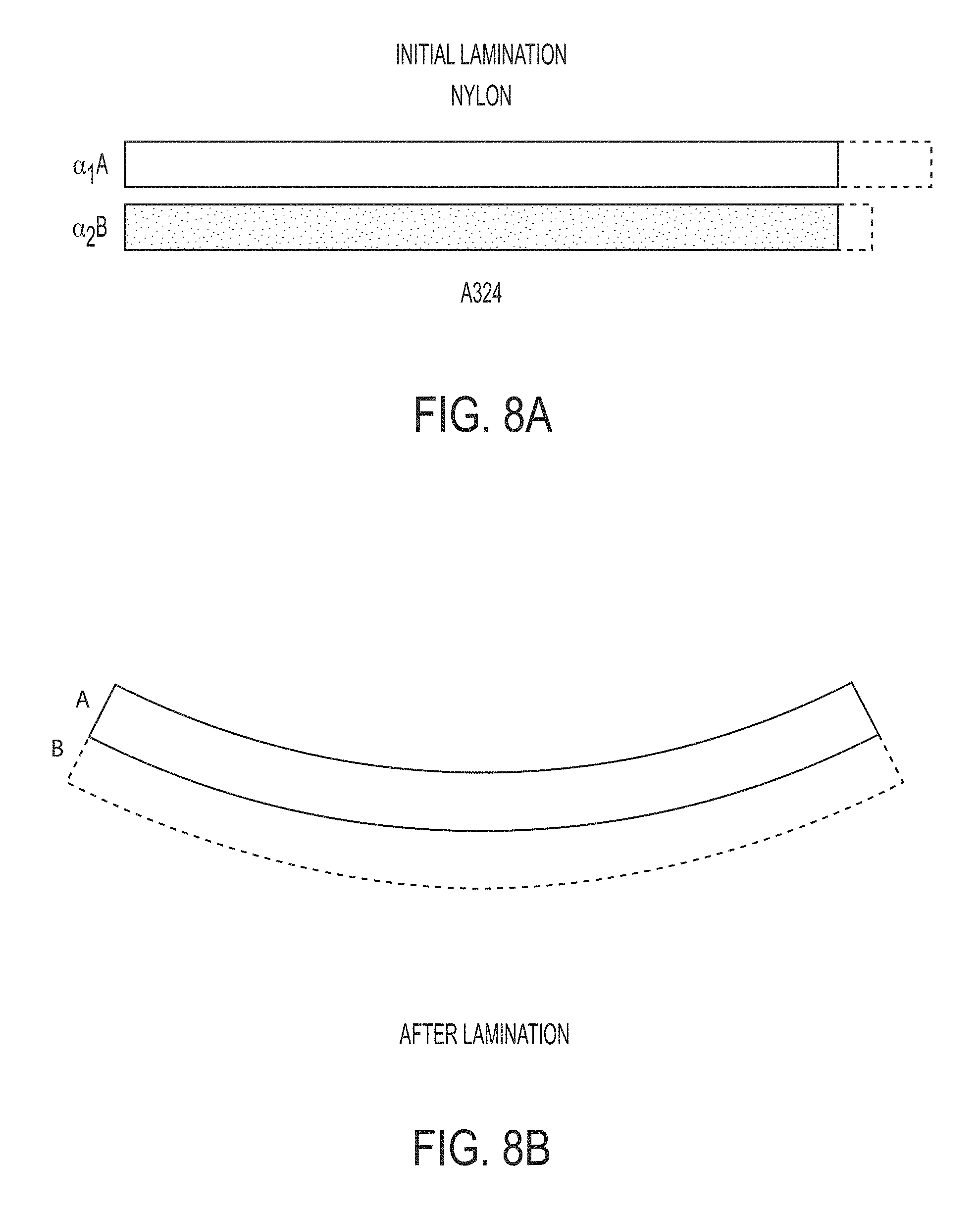
D00013
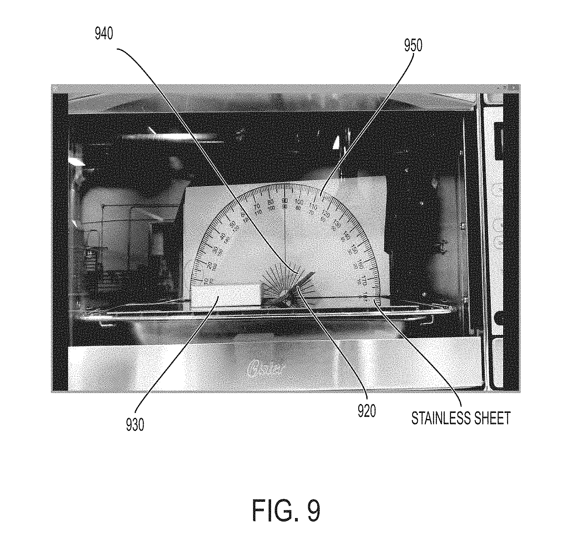
D00014
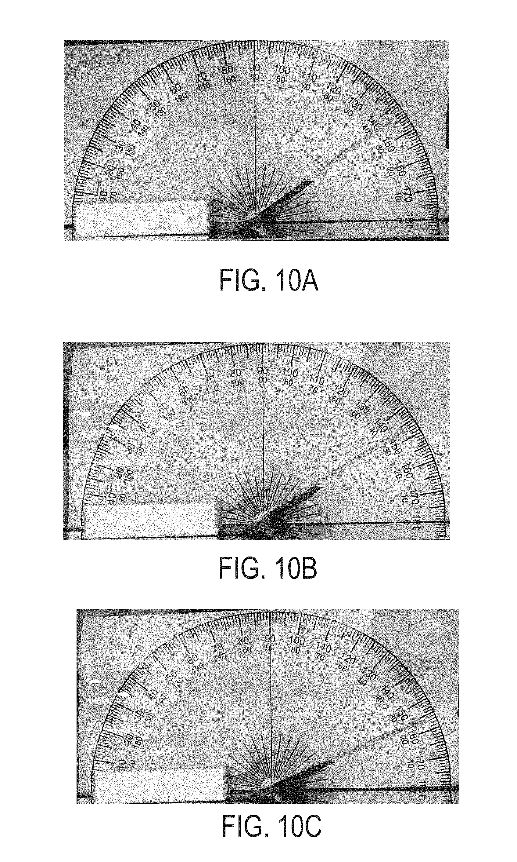
D00015
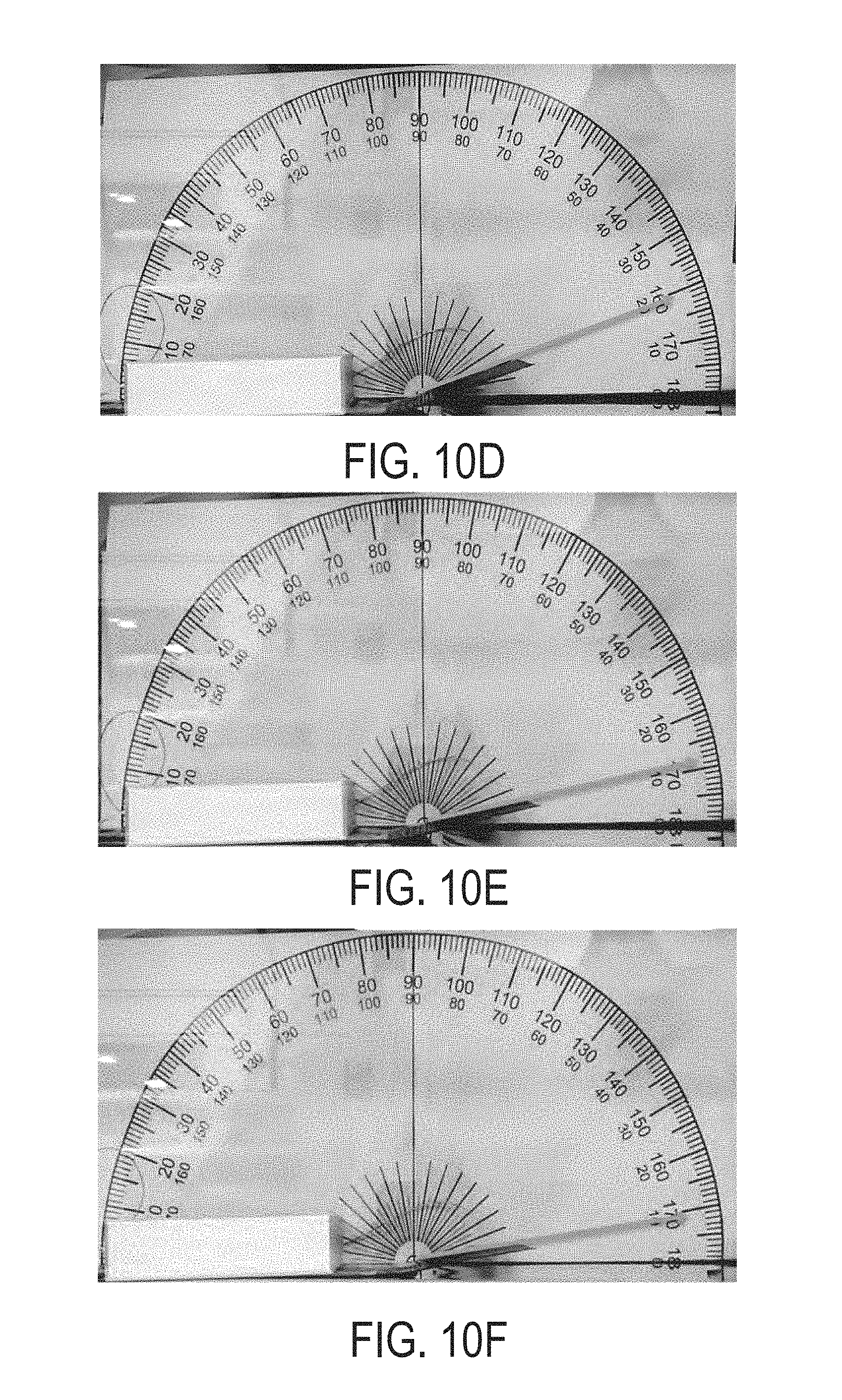
D00016
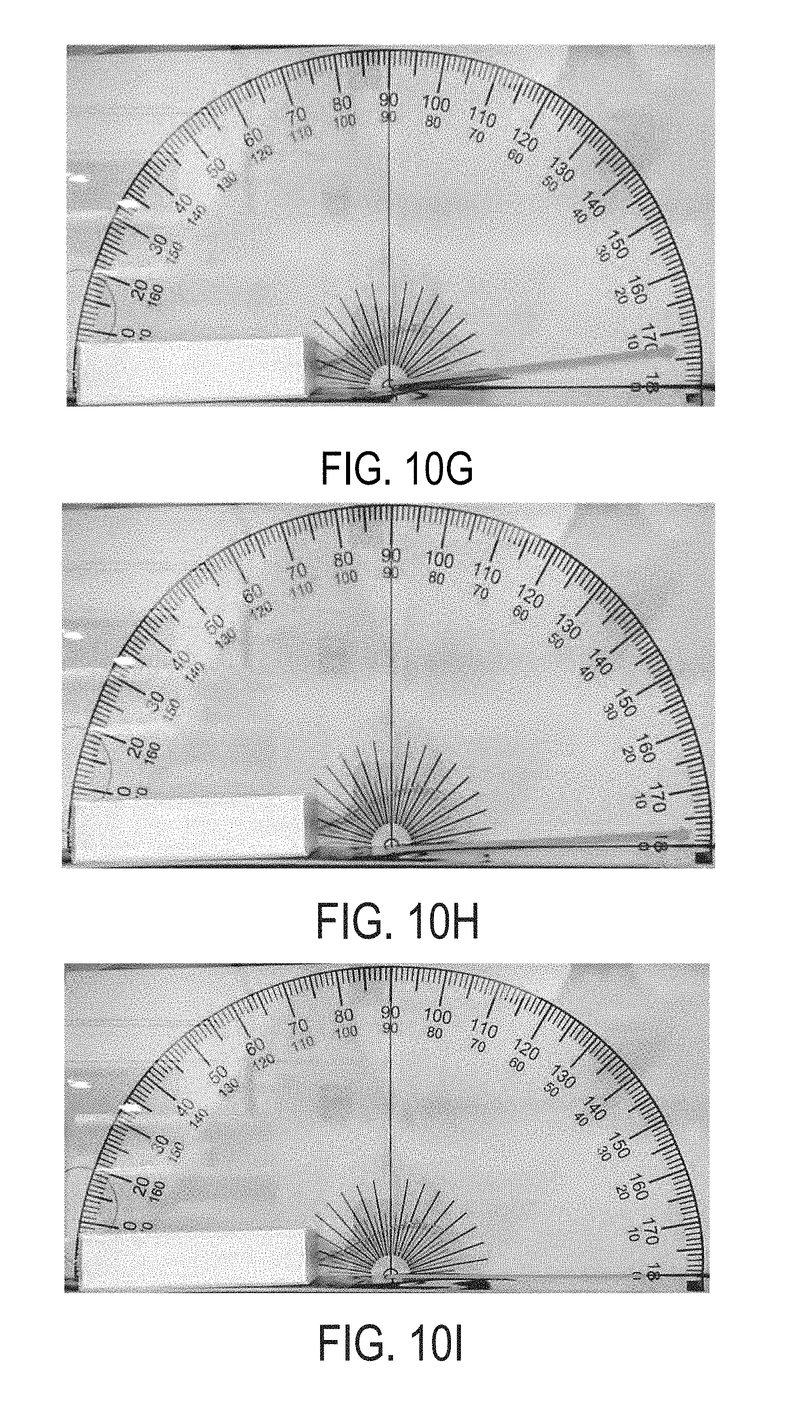
D00017
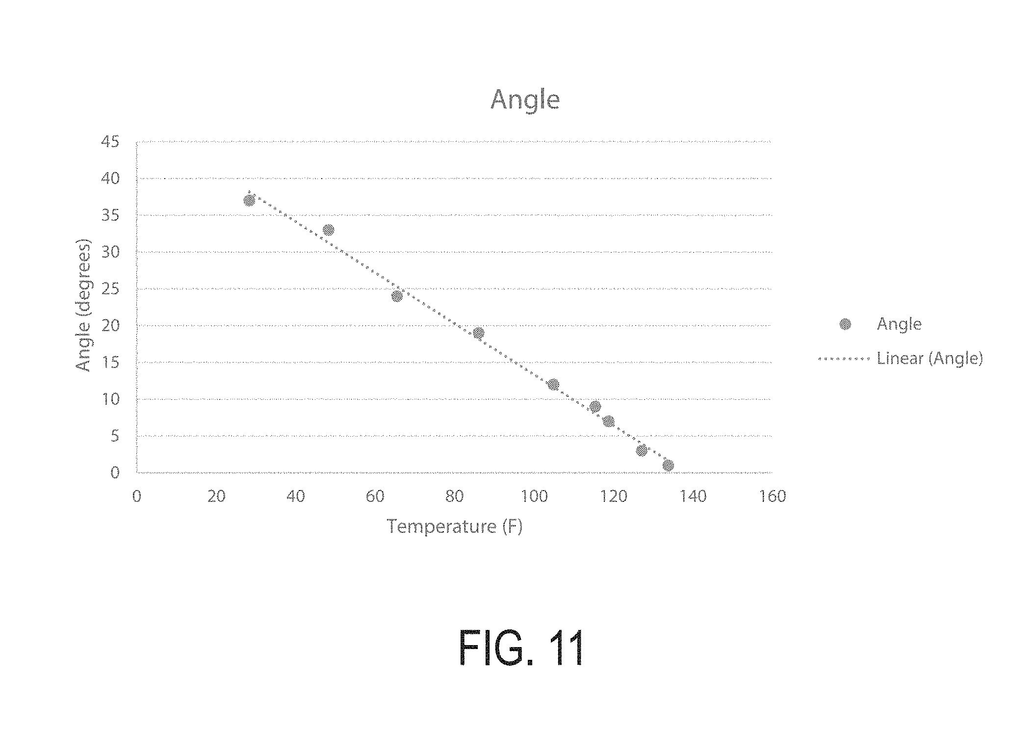
D00018
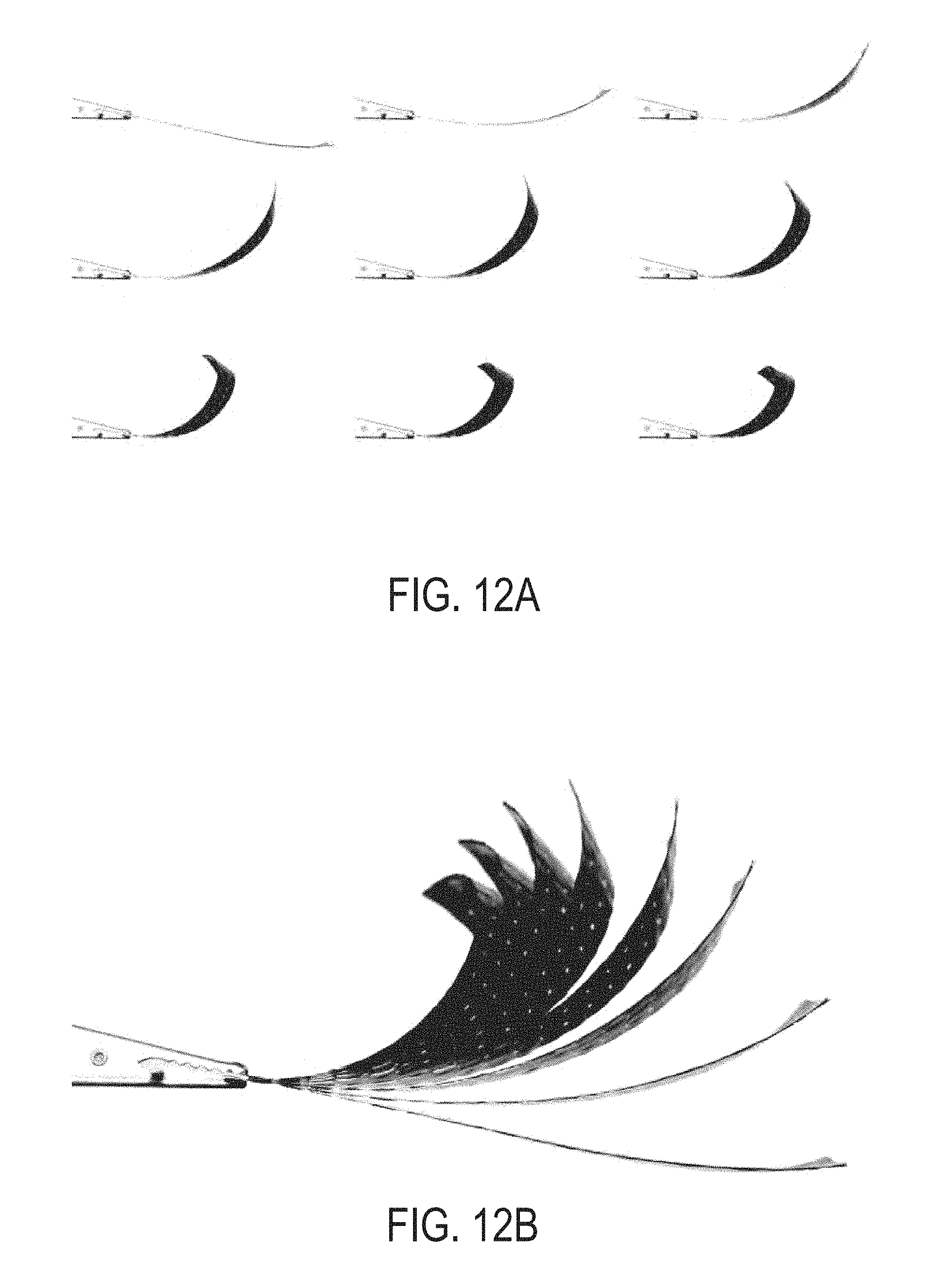
D00019
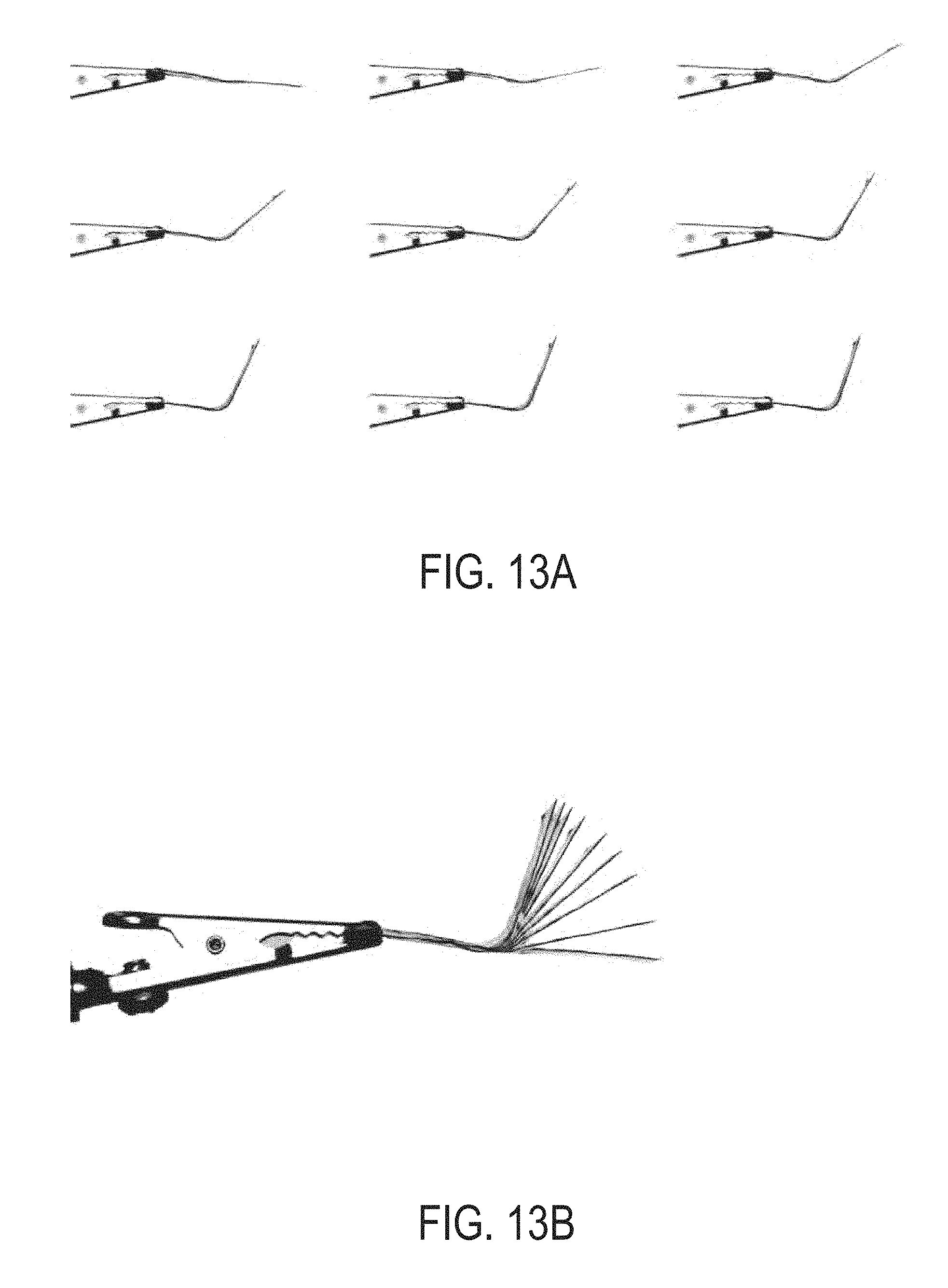
D00020
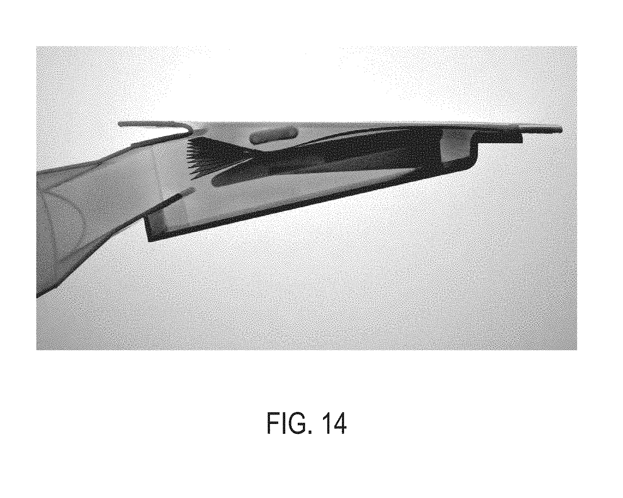
D00021
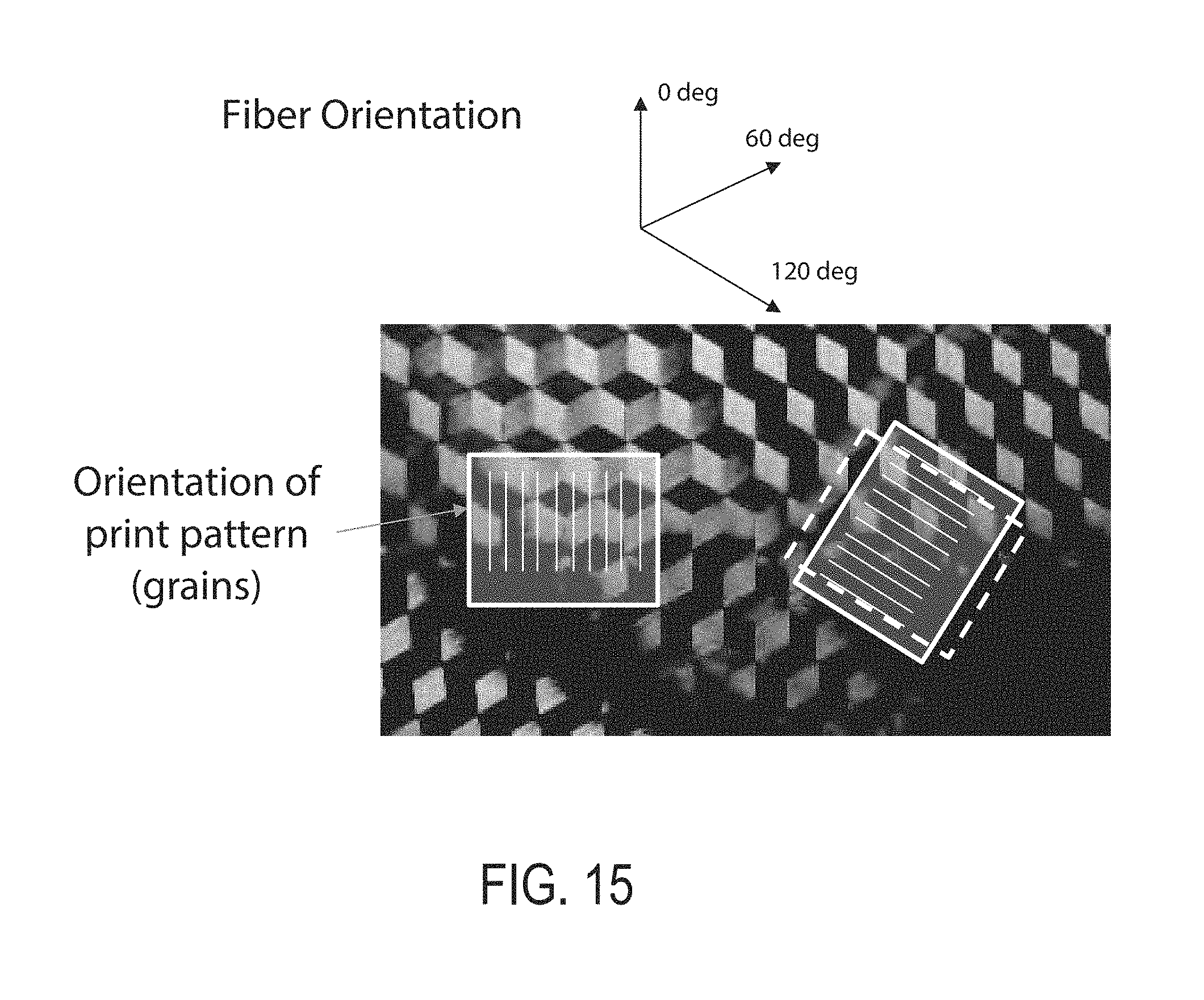
D00022
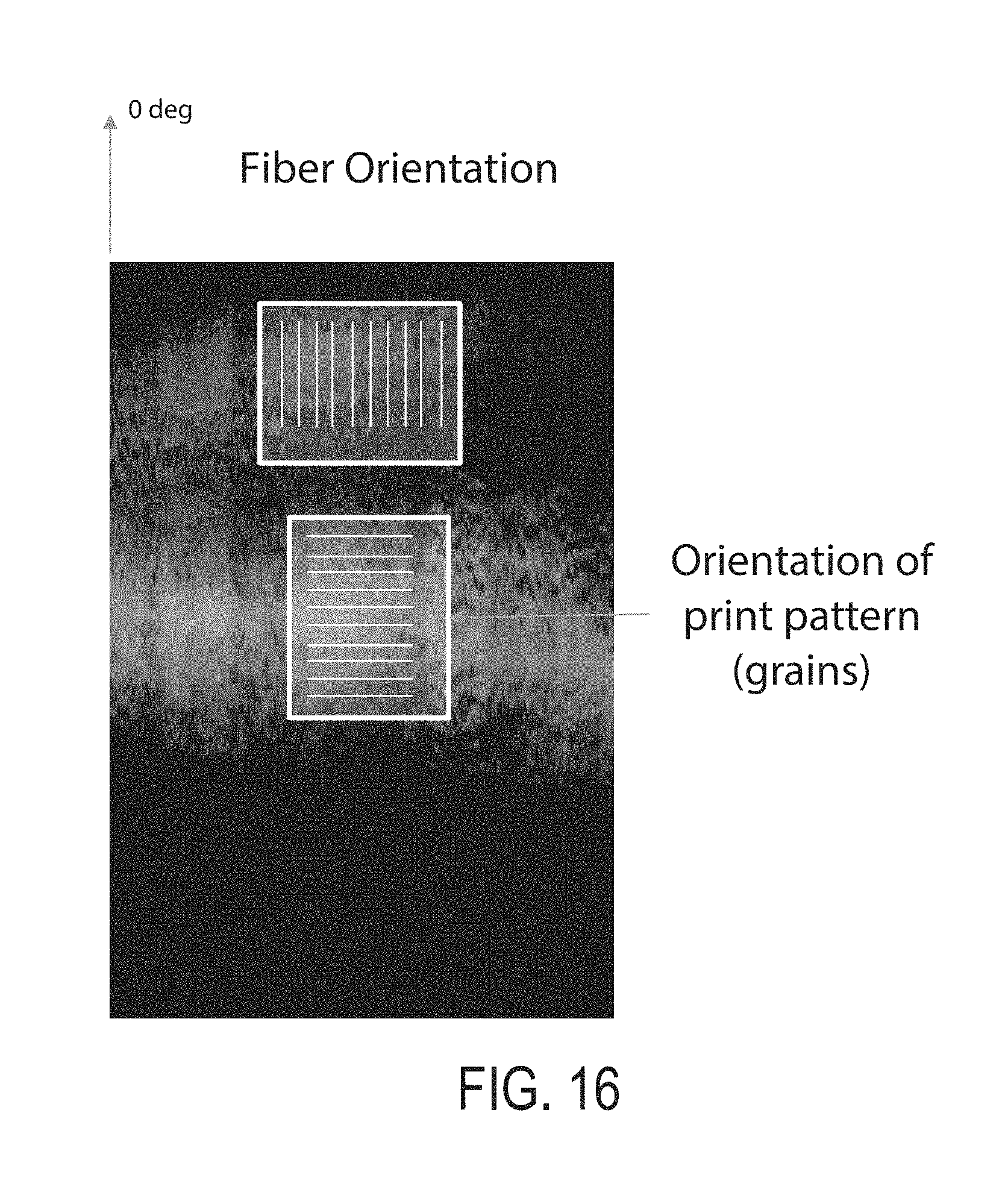
D00023
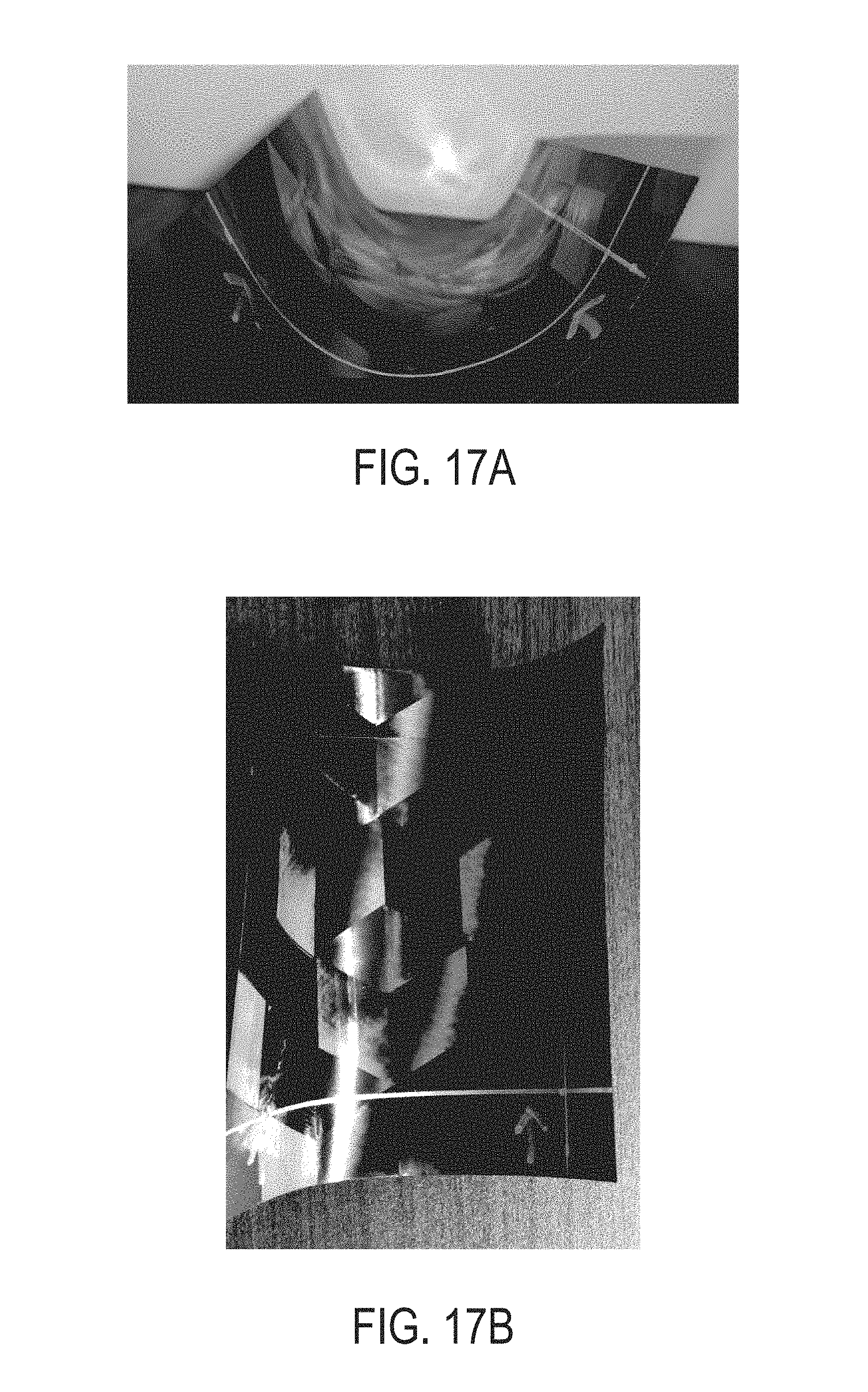
D00024
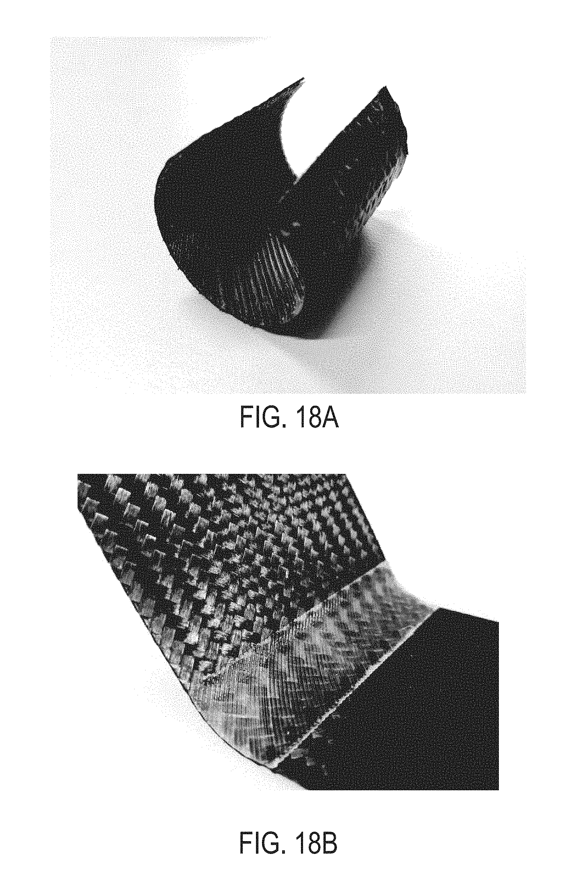
D00025
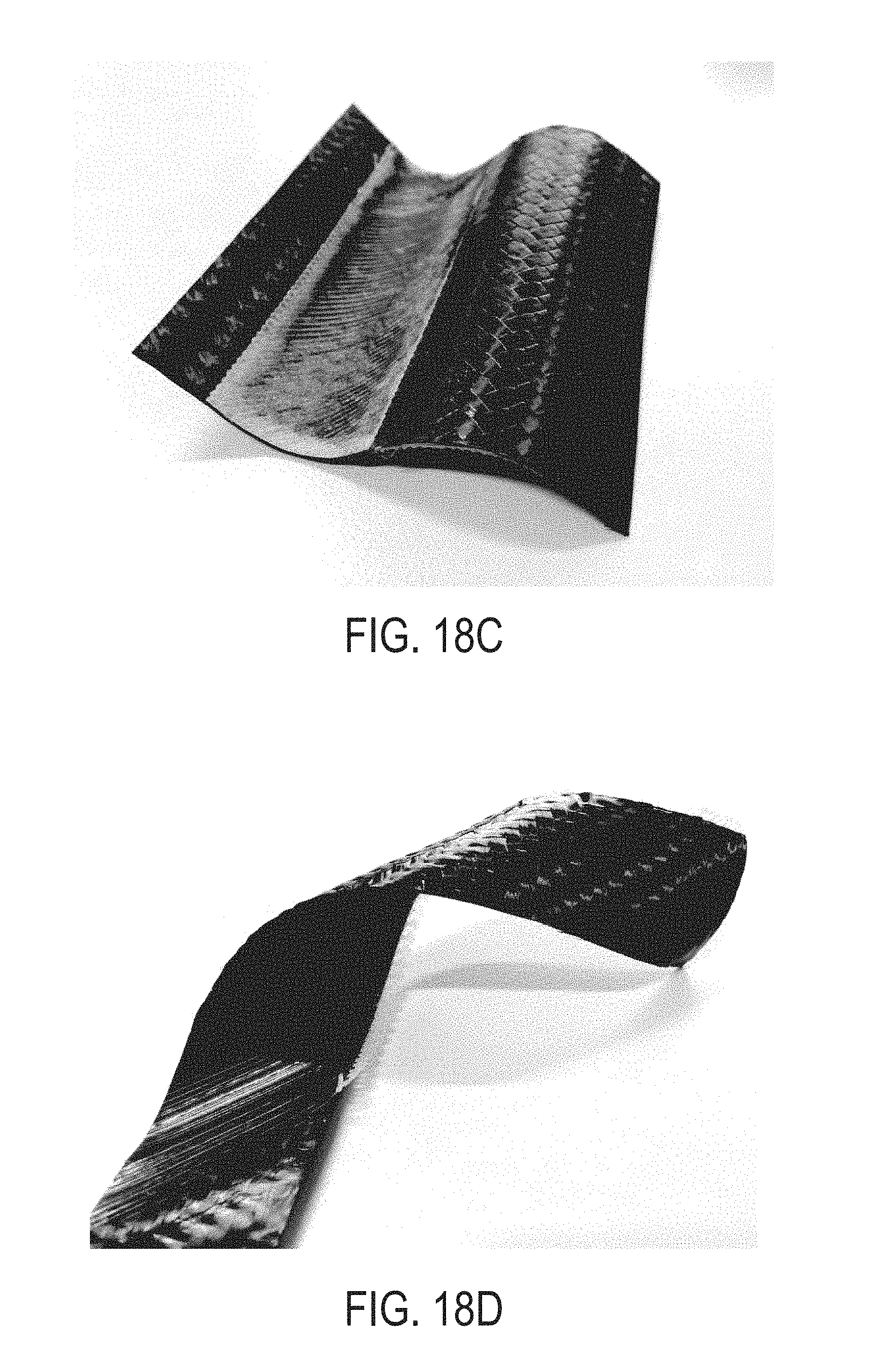
XML
uspto.report is an independent third-party trademark research tool that is not affiliated, endorsed, or sponsored by the United States Patent and Trademark Office (USPTO) or any other governmental organization. The information provided by uspto.report is based on publicly available data at the time of writing and is intended for informational purposes only.
While we strive to provide accurate and up-to-date information, we do not guarantee the accuracy, completeness, reliability, or suitability of the information displayed on this site. The use of this site is at your own risk. Any reliance you place on such information is therefore strictly at your own risk.
All official trademark data, including owner information, should be verified by visiting the official USPTO website at www.uspto.gov. This site is not intended to replace professional legal advice and should not be used as a substitute for consulting with a legal professional who is knowledgeable about trademark law.